SECTION 3 - COMPONENT SERVICING
3121741 – JLG Lift – 3-17
Contactor Solenoid Replacement
(See Figure 3-20. - Items 7 and 8)
(See Figure 4-5. - motor contactor 1 and motor contac-
tor 2 for wiring connections, if necessary)
1. Place machine in a clear work area.
2. Rotate the platform up into the machine mainte-
nance position and lock the gas strut.
3. Remove the base frame cover.
4. Disconnect machine power by removing the
battery (+) positive terminal from the battery (+)
positive post.
5. Disconnect the motor contactor 1 and/or motor
contactor 2 cables and wiring from the contactor
solenoids.
6. Remove the mounting bolts and nuts from the
contactor solenoids.
7. Replace the contactor solenoid, install reversing
the steps above.
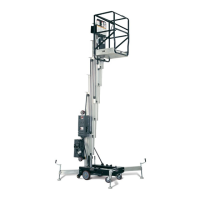
Battery Charger Operation
The battery charger is located under the base frame cover
beneath the platform. (See Figure 3-21.). To access the
charger, see Figure 5-2.
Figure 3-21. Battery Charger
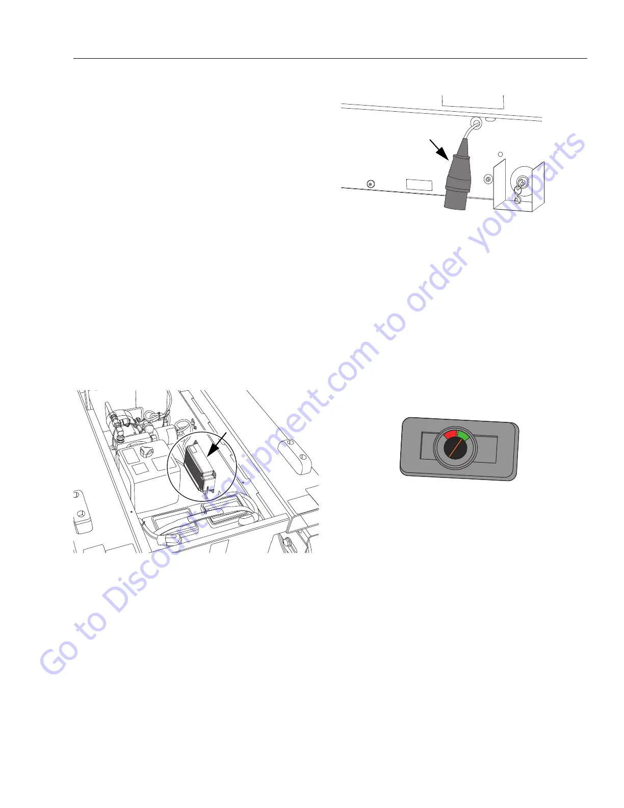
The charging AC input cable is located on the left side of
the machine base (see Figure 3-22.). Plug into a compati-
ble AC power supply, see charger specifications in Table 5-
3 on page 5-3.
Figure 3-22. Charger AC Input Cable
The battery charge level can be monitored at the platform
control box - battery charge indicator see Figure 3-23. or
by observing the LEDs on the front of the battery charger,
see Figure 3-24.
To display current battery charge status on the platform
control - battery charge indicator - both the ground and
platform control, emergency stop switches must be set to
the ON position, and the enable button on the side of the
platform control must be momentarily pressed in. When
the indicator is at the top of the GREEN area that indicates
a full charge. When the indicator is in the RED area this
indicates power is getting low and batteries will soon
need recharged.
Figure 3-23. Battery Charge Indicator
(Located near the top of the Platform Control Box)
If observing the charger LEDs, ensure the GREEN LED
(front of charger) illuminates. and stays lit.
The adjacent AMBER LED has three modes (see Figure 3-
24.).
1. Rapid flash, indicates maximum charge rate.
(Note, when switching charger on, the amber
light must rapid flash. If not, there is a fault,
check fuse and connections).
2. Slow pulse, indicates slower charging.
3. Continuous illumination indicates float charge.
Both LEDs go “off” when fully charged.
The battery charger can be connected to the AC power
supply at any time or left for extended periods.
Go to Discount-Equipment.com to order your parts