Page 17
John Bean BFH 1000 Operators Manual
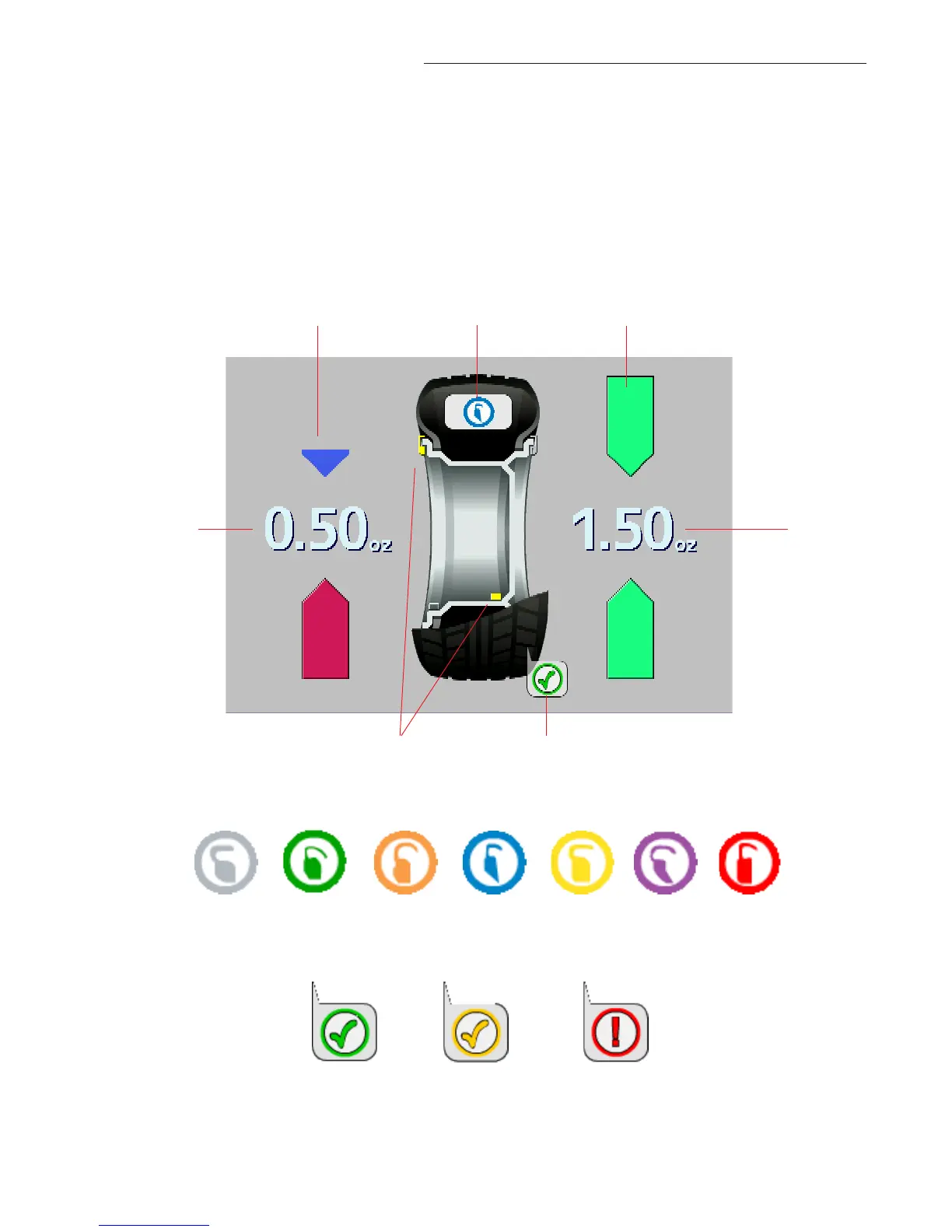
Figure 16b - Color Weight Selections
6.2 BALANCE SCREEN DESCRIPTION
Refer to Figure 16a below for an example of a typical balance screen. The wheel displayed has
been profiled as a rim which will accept a clip weight on the left side and a stick-on weight on the
right side. A Blue weight is the correct clip-on selection for this application. The Clip weight will be
placed at top dead center when the arrows indicate green. The stick-on weight is placed as indi-
cated by the laser pointer. The operator selects the desired mode as indicated by the yellow weight
icons, such as clip-stick as shown in the example below. Subsequent wheels will use the same
mode. Tread depth is measured to be within tolerance in the example.
Figure 16c - Tread Depth Indicators
Good
Marginal
Tread depth is
beyond threshold
Outside
Position
Indicator
Inside
Position
Indicator
Color Weight
Indicator
Inside
Weight
Amount
Outside
Weight
Amount
Tread Depth
Indicator
Mode/Placement
Indicators
Figure 16a