Page 11
Icon 5 Icon 6
Icon 7a
Icon 8 Icon 9
Icon 7b
Icon 1 Icon 2
Icon 3
Icon 4
Icon 10
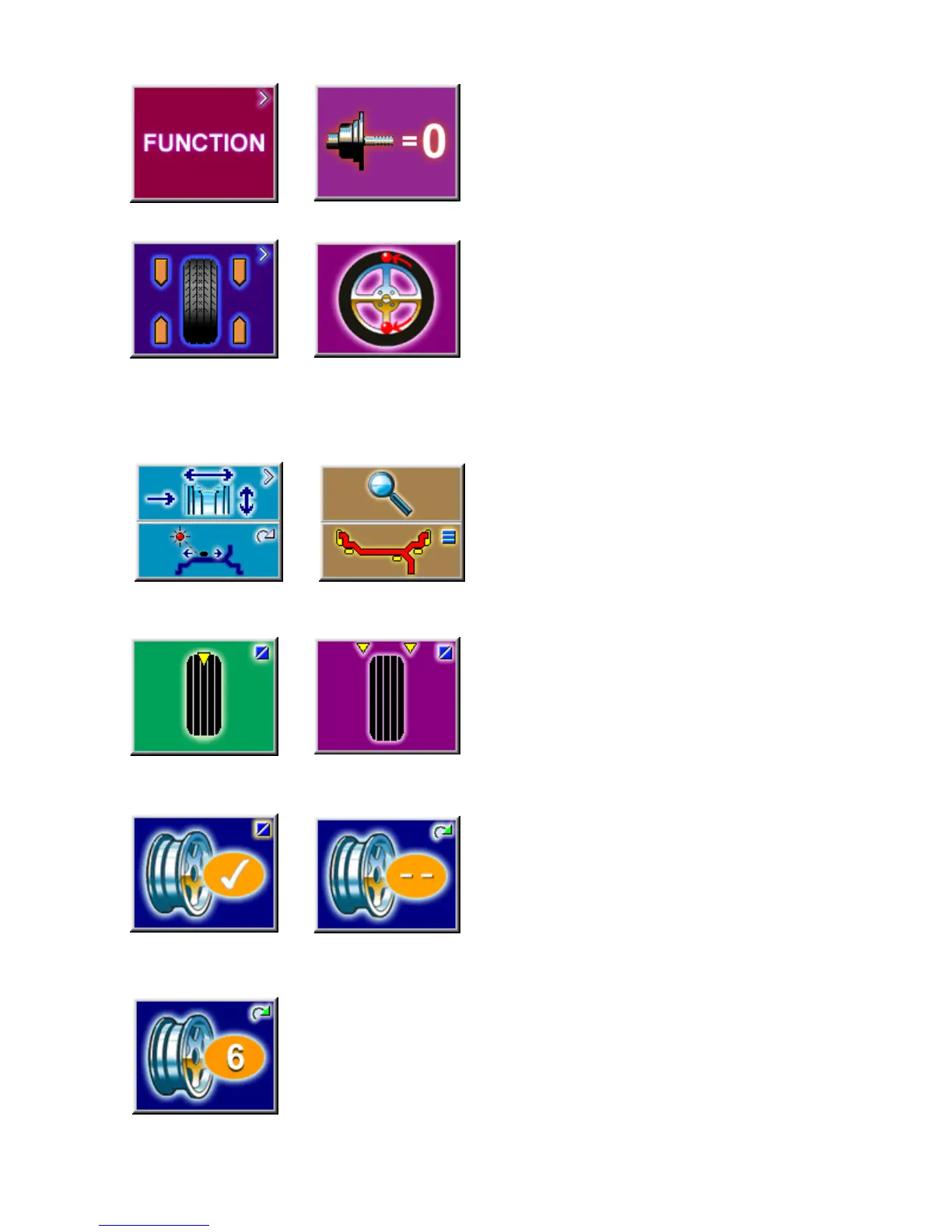
3.2.2 MAIN MENU FUNCTIONS
Icon 1 Change to the Function screen
Icon 2 Perform adapter compensation run
Icon 3 Change to the Balancing screen
Icon 4 Change to the OPTIMIZATION MENU
3.2.3 BALANCING
Icon 5 Toggle switch, two functions:
Pressed on top:
View and/or edit Data Input (wheel parameters)
Pressed on bottom:
Move the laser position pointer to the desired
location. Button must be held down as the shaft is
rotated. (only when stick-on weights are selected)
Icon 6 Toggle switch, two functions; reading only as
long as the key is pressed (quick reading):
Pressed on top:
Precision reading of unbalance, no suppression of
minor unbalance readings.
Pressed on bottom:
Toggles through possible placement locations of
weight placement for conventional balancing run.
Icons 7a and 7b Select static unbalance or Select
dynamic unbalance
Icon 8 Number of spokes has been selected and
entered.
Icon 9 Number of spokes has not been detected and
must be entered manually if required. Hold the F key
while rotating the shaft until the desired value is
displayed.
Icon 10 Wheel with 6 spokes selected