EasyManuals Logo

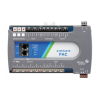
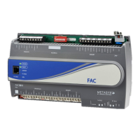
Johnson Controls FAC4911 User Manual

Johnson Controls FAC4911
22 pages
To Next Page IconTo Next Page
To Previous Page IconTo Previous Page
Page #11 background imageLoading...
Page #11 background image
Termination diagrams
A set of Johnson Controls termination diagrams provides details for wiring inputs and outputs to the controllers. See the
figures in Table 6 in this section for the applicable termination diagrams.
Table 6: Termination details
Type of field
device
Type of Input/
Output
Termination diagrams
Temperature
Sensor
UI
Voltage Input -
External Source
UI
Voltage Input -
Internal Source
UI
Voltage Input
(Self-Powered)
UI
FAC4911 Advanced Application Field Equipment Controller Installation Guide 11

Questions and Answers:

Question and Answer IconNeed help?

Do you have a question about the Johnson Controls FAC4911 and is the answer not in the manual?

Johnson Controls FAC4911 Specifications

General IconGeneral
BrandJohnson Controls
ModelFAC4911
CategoryController
LanguageEnglish

Related product manuals