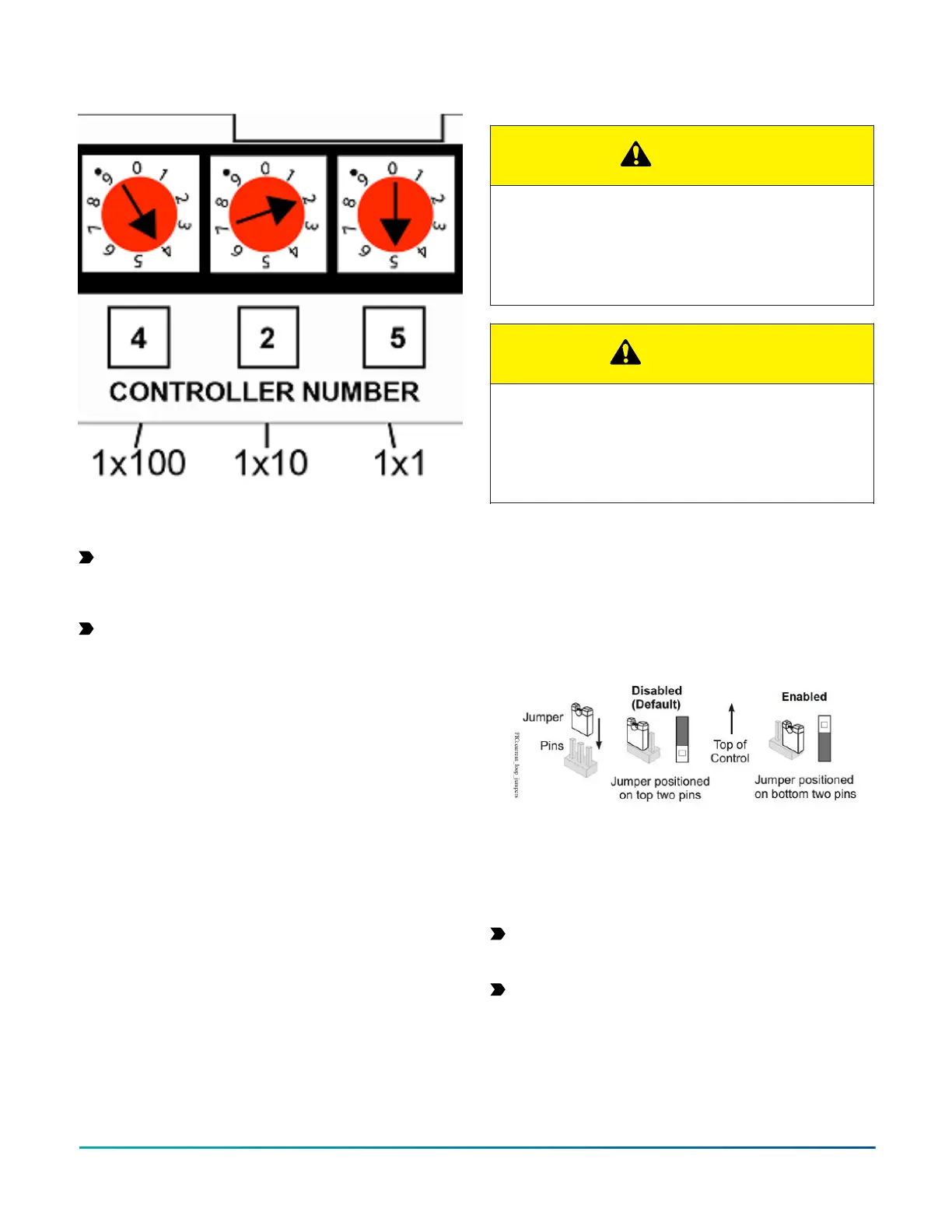
Figure 7: Rotary switch for setting controller numbers
Removing the Controller cover
About this task:
Important: Electrostatic discharge can damage
controller components. Use proper electrostatic
discharge precautions during installation, setup, and
servicing to avoid damaging the controller.
Important: Disconnect all power sources to the
controller before you remove the cover and change
the position of any jumper on the controller. Failure
to disconnect power before changing a jumper can
result in damage to the controller and void any
warranties.
The controller cover is held in place by four plastic latches
that extend from the base and snap into slots on the
inside of the housing cover.
To remove the controller cover, complete the following
steps:
1. Place your fingertips under the two cover lift tabs
on the sides of the housing cover and gently pry
the top of the cover away from the base to release
the cover from the two upper latches.
2. Pivot the top of the cover further to release it from
the lower two latches.
3. Replace the cover by placing it squarely over the
base, and then gently and evenly push the cover
on to the latches until they snap into the latched
position.
Setting the Input Jumpers
CAUTION
Risk of Electric Shock:
Disconnect supply power to the field controller before
attempting to adjust the Binary Output Source Power
Selection Jumpers. Failure to disconnect the supply
power may result in electric shock.
ATTENTION
Risque de décharge électrique
Débrancher l'alimentation de l'controller avant tout
réglage du Binary Output Source Power Selection
Jumpers. Le non-respect de cette précaution risque
de provoquer une décharge électrique.
UI current loop jumpers
The UI current loop jumpers are located on the circuit
board under the controller cover near the UI terminals.
When a UI is defined in the system software as a 4-20
mA Analog Input, set the UI's current loop jumper to the
Enabled position as in Figure 8.
Figure 8: Current loop jumper positions
Setting the current loop jumper to the Enabled position
connects an internal 100 ohms resistor across the UI
terminals, which maintains the 4–20 mA current loop
circuit even when power to the controller is interrupted or
off.
Important: Current loop jumpers must be in the
Disabled (default) position for all UIs that are not set
up to operate as 4–20 mA analog inputs.
Important: A current loop jumper must be in the
Enabled position to maintain a closed 4-20 mA
current loop.
The following table identifies the current loop switches
associated with each UI on the controller.
FAC4911 Advanced Application Field Equipment Controller Installation Guide 17