Important: Do not exceed the controller electrical
ratings. Exceeding controller electrical ratings can
result in permanent damage to the controller and
void any warranty.
Important: Use copper conductors only. Make
all wiring in accordance with local, national, and
regional regulations.
Important: Electrostatic discharge can damage
controller components. Use proper electrostatic
discharge precautions during installation, setup, and
servicing to avoid damaging the controller.
For information on configuring and wiring a BACnet/SC
or BACnet/IP network, refer to the Metasys IP Networks for
BACnet/ IP Controllers Configuration Guide (LIT-12012458).
For detailed information on configuring and wiring a
SA Bus, refer to the MS/TP Communications Bus Technical
Bulletin (LIT-12011034).
Network topology
FAC4911 controllers may be connected to a building
automation network in multiple ways: as daisy-chained
devices, as part of a star (also called home run) network,
or as part of a ring network.
To daisy-chain FAC4911 controllers, connect the
controllers to the bus supervisor in a chain with the
Ethernet cable connecting to the FAC4911 at the ETH1
or ETH2 port and connecting to the next device from the
other port. Benefits of daisy-chained networks are that
they require less physical wiring and new devices can be
added easily to the network.
In a star network, each FAC4911 controller is connected
by ETH1 or ETH2 directly back to a main switch. This
configuration reduces the possibility of network failure
but requires more wiring to install.
A ring network is a chain of controllers virtually closed
by a software component in an Ethernet switch. Not
all switches support the ring topology. The dual-port
controller from Johnson Controls supports Media
Redundancy Protocol (MRP). MRP allows a chain of
Ethernet devices to overcome any single communication
failure, with a recovery time faster in a BACnet system.
For more information about network topologies for the
BACnet/SC or BACnet/IP Controllers, refer to the Metasys
IP Networks for BACnet/IP Controllers Configuration Guide
Technical Bulletin (LIT-12012458).
Terminal blocks and bus ports
Input and Output terminal blocks
The fixed input terminal blocks are located on the bottom
of the controller, and the output terminal blocks are
located on the top of the controller.
SA Bus terminal block
The SA Bus terminal block is a brown, removable, 4-
terminal plug that fits into a board-mounted jack.
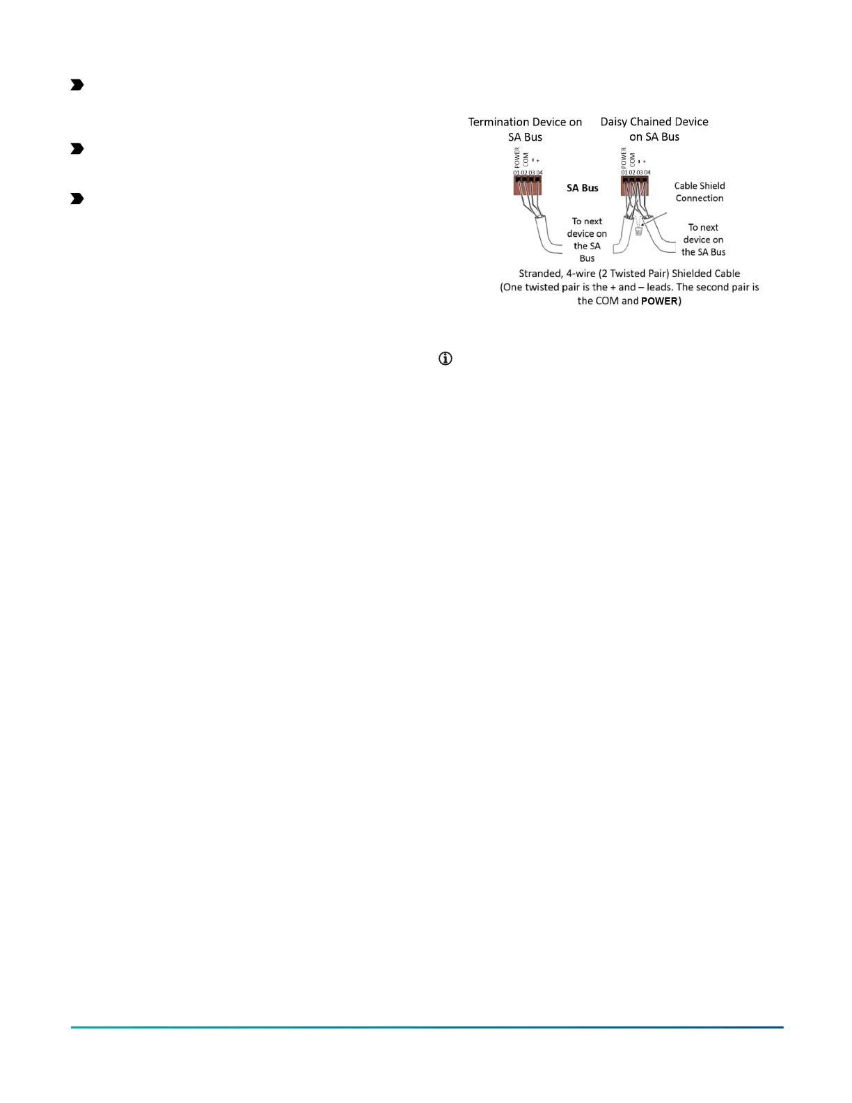
Wire the removable SA Bus terminal block plugs on the
controller, and other SA Bus devices in a daisy-chain
configuration using 4-wire twisted, shielded cable as
shown in Figure 4.
Figure 4: SA Bus terminal block wiring
Note: The SA PWR terminal supplies 15 VDC. The SA
PWR terminal can be used to connect (daisy chain)
the 15 VDC power leads on the SA bus.
SA Bus Port
The Sensor (SA Bus) port on the bottom of the controller
is an RJ-12, 6-position modular jack that provides a
connection for the VAV Balancing Tool, specified network
sensors, or other SA Bus devices with RJ-12 plugs.
A DLK0350 or DIS1710 Local Controller Display can be
connected to the SA Bus port also.
The Sensor port is connected internally to the SA bus, but
cannot be used at the same time as the terminal block.
Supply power terminal block
The 24 VAC supply power terminal block is a gray,
removable, 3-terminal plug that fits into a board-mounted
jack on the top right of the controller.
Wire the 24 VAC supply power wires from the transformer
to the HOT and COM terminals on the terminal plug as
shown in Figure 5. Do not use the middle terminal on the
supply power terminal block.
FAC4911 Advanced Application Field Equipment Controller Installation Guide 5