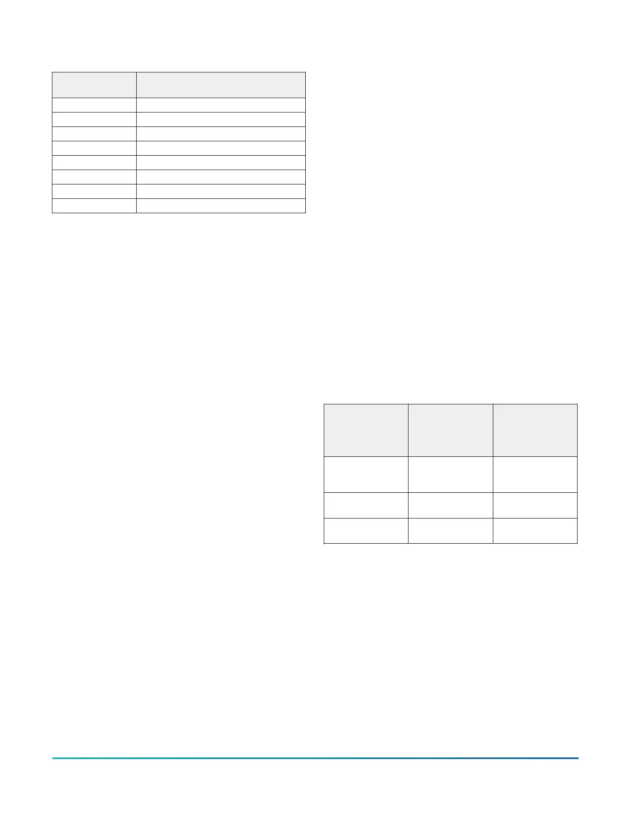
Table 7: UI Inputs and Jumper Labels
Universal Input
Label
Jumper Label on Circuit Board
IN1 J5
IN2 J6
IN3 J7
IN4 J8
IN5 J9
IN6 J10
IN7 J11
IN8 J12
Input/Output Wiring Validation
The FAC4911 controllers ship with a default state that
can assist in validating the wiring of the input and output
terminals before downloading an application file. When
the controller is powered on in this state, the Fault LED
will flash in a pattern of two quick blinks and then a long
pause (see LED status and description table).
To make use of this feature, ensure the rotary switches
are set to the chosen controller number and wire the
input and output terminals. Apply power to the FAC
controller and connect to the device with either a MAP
Gateway, a DLK0350 Local Display, or DIS1710 Local
Display to view the points in the controller. The FAC
controller will report an Operational status even though
there is no true application loaded. CCT will not be able
to commission or upload the device as a result until a
true application is downloaded. The application name
displayed will be the controller number followed by the
model of the controller and “Default State”.
For example, a FAC4911 controller whose rotary switches
are set to 8 would have the default state application name
of “8-FAC4911 Default State”.
The default state creates I/O points for all connections
on the input and output terminals. It assumes all
Universal Inputs (UIs) are Nickel temperature sensors. All
Configurable Outputs (COs) are treated as Binary Outputs
(BOs) with an initial value of 0. The default state also takes
input from a Network Sensor at address 199. If there is
no connected Network Sensor, the startup of this default
state will be delayed by 30 seconds as the controller
attempts to establish connection with the sensor.
Commissioning Field Controllers
You commission controllers with the CCT software.
The controller can be connected in one of three ways:
either through Supervisor Passthru using an engine at
release 9.0 or greater, MAP 4.2+/BACnet Router (Mobile
Access Portal (MAP) Gateway at version 4.2 or above)
or Direct Ethernet connection to the controller. Refer
to the Controller Tool Help (LIT-12011147) and Controller
Provisioning with Tools (LIT-12013247) for detailed
information about commissioning field controllers.
Firmware Package File
The MS-FCP-0 equipment controller firmware package
files are required for CCT to configure and commission
the controllers. The firmware package files also allow you
to upgrade an existing XPM or IOM to the latest firmware
release available for that expansion module.
Beginning at CCT Release 13, the firmware package files
are orderable separately; they are not included with CCT.
They are obtained from the Metasys software licensing
portal, and are loaded and licensed on the computer/
server that is running CCT.
For additional information about the firmware
package files, refer to the CCT Installation Instructions
(LIT-12011259).
Setting up a local display
The FAC4911 controller does not have an integral display,
but you can connect it to a DIS1710 or DLK0350 Local
Controller Display. If the display is configured with a local
password, the equipment controller and display must be
running compatible firmware versions. If the display is
not configured with a local password, it is compatible with
equipment controllers at any firmware version. See the
following table for further details:
Table 8: Equipment Controller and display
compatibility for displays configured with a local
password
Display model
and firmware
version
Controller
running 10.x
firmware or
greater
Controller
running 9.x
firmware or
earlier
DLK0350 running
10.x firmware or
greater
Compatible Not compatible
DLK0350 running
9.x firmware
Not compatible Compatible
DIS1710 running
6.2 firmware
Not compatible Compatible
For detailed information about setting up and operating
a remotely connected display, refer to the DIS1710 Local
Controller Display Technical Bulletin (LIT-12011270) or Local
Controller Display User Guide (LIT-12013762).
Troubleshooting Field Controllers
Observe the Status LEDs on the front of the controller and
see the following table to troubleshoot the controller.
FAC4911 Advanced Application Field Equipment Controller Installation Guide18