RWF II ROTARY SCREW COMPRESSOR UNITS
OPERATION
070.610-IOM (JUN 11)
Page 22
and/or heat tracing of the compressor lube oil systems is
highly recommended.
When low ambient temperatures (below +20°F) are a pos
sibility, it is recommended that lube oil lines, oil lters, oil
pumps, and oil coolers be heat traced and insulated.
Freezeup protection must also be provided for all water
cooled equipment
SUCTION CHECK VALVE
POWER ASSIST KIT
Low temperature booster compressor applications require
hot gas to assist the suction check valve closure for RWF II
models 496, 676, 856, and 1080. This is accomplished by using
the high pressure discharge gas from the high pressure side
of the system (power assist kit).
The power assist kit (Figure 28) is factory installed with the
discharge gas pressure being supplied from the high stage
discharge gas. The kit consists of a strainer, mounted and
wired solenoid valve, timer, and metering valve. The timer
limits the high pressure gas feed to the suction check valve
to thirty seconds via the solenoid valve. This is sufcient
time to warm the suction check valve piston and provide
proper operation. The metering valve is provided for use as
a service valve and to allow discharge gas ow regulation to
prevent excessive force and resulting closure "hammering".
The valve should be adjusted accordingly to prevent such
an occurrence.
POWER ASSIST TO BE CONNECTED TO
CONN IN CENTER OF MV END PLATE
HIGH PRESSURE GAS FROM HIGH
SIDE COMPRESSOR DISCHARGE
M–1
C–1
3/8 OD
1/2
1/2
1/4
STR-4
S
YY
7
Figure 28 - Power Assist Kit
BALANCE PISTON PRESSURE REGULATOR
A Balance Piston Pressure Regulator may be required on
Models 496 – 1080 to reduce the extended overbalance from
the thrust balance piston at part load.
High-Stage SB-2 Oil Supply Line Diagram, Figure 29, shows
the three additions described below arranged in parallel.
PRESSURE-REGULATING VALVE: Discharge pressure deter
mines compressor thrust balance. The proper setting for the
pressureregulating valve is 50 psi (±15) below DISCHARGE
pressure when slide valve is less than 65%.
SOLENOID VALVE: Energizing, or opening, the solenoid valve
pressurizes the balance piston with full oil pressure from the
oil manifold, bypassing the A4ALE Pressure Regulating Valve.
Deenergizing, or closing, the solenoid valve pressurizes
the balance piston with oil pressure regulated by the A4ALE
Pressure Regulating Valve.
3. Connect the power supply.
4. Release down arrow and up arrow push buttons.
5. When the display on ICAD (Figure 22) is alternating be
tween showing: CA and A1 the factory resetting is complete.
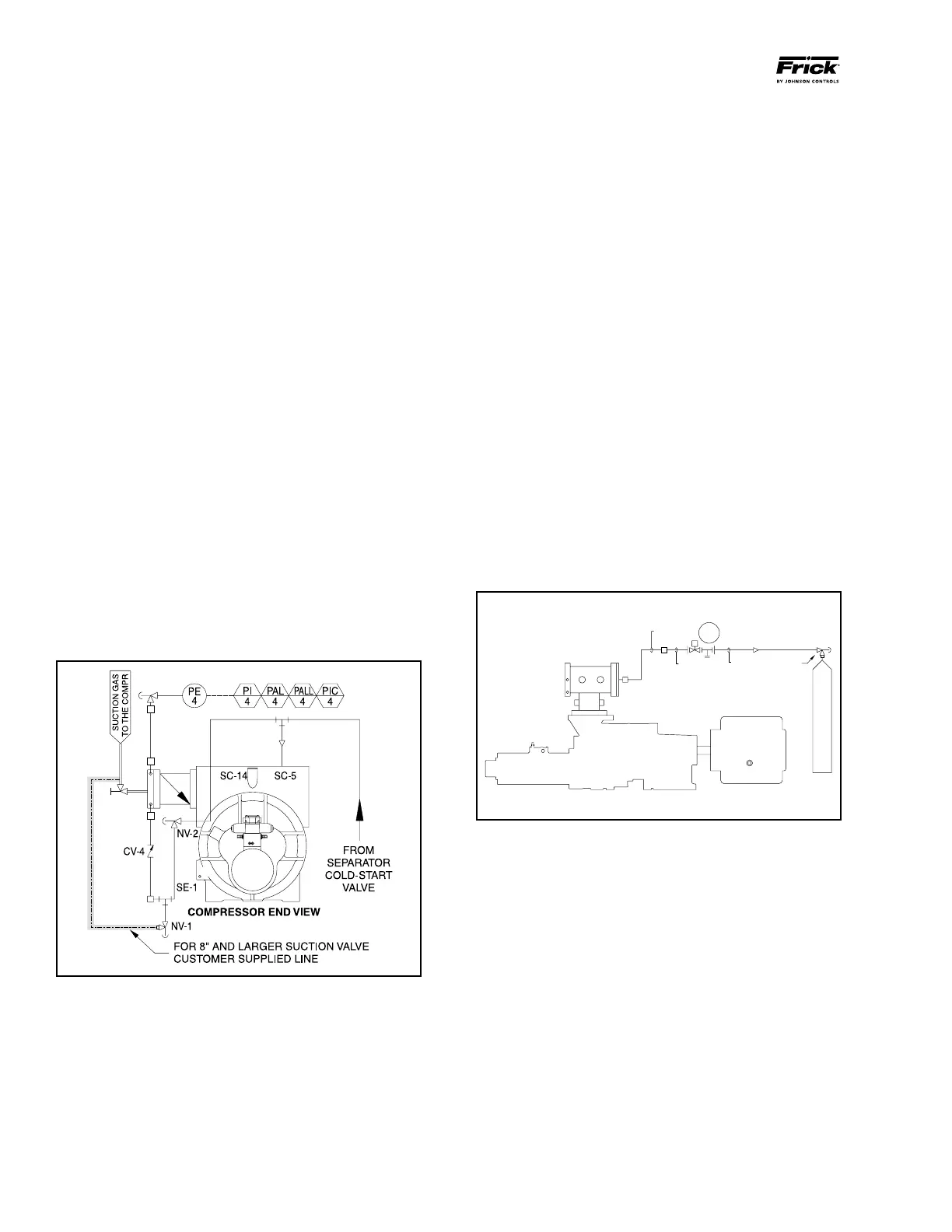
SUCTION CHECK VALVE BYPASS
The RWF II unit is equipped with a lowpressuredrop suc
tion check valve bolted directly to the compressor housing.
Units that have an 8" stop valve or larger should be piped as
shown in the shaded area of Figure 27. During normal opera
tion, valve NV1 is closed. This is a pumpout connection
to allow refrigerant removal to the system suction prior to
evacuation for servicing. Valve NV2 must be open in most
systems at all times. It should normally be cracked open to
allow the oil separator to slowly bleed down to approxi-
mately system suction pressure when the unit is stopped
(having this valve cracked open allows the compressor drive
motor to have an easier start, and the discharge check valve
will seat more tightly). If the drive coupling backspins, start
closing the valve until the backspin stops. If the separator oil
level foams excessively on shutdown, NV2 should be closed
slightly. If the separator takes more than 20 – 30 minutes to
equalize to suction pressure after shutdown, NV2 can be
opened slightly. See Figure 27.
Check valve CV4 is installed on all RWF II packages. On
highstage systems, check valve CV4 is installed with a
45 psi spring to avoid the possibility of backfeeding to a
shutdown compressor from a common economizer vessel.
On booster systems, check valve CV4 is installed with a
25 psi spring to avoid the possibility of air ingress into the
system, if the system suction pressure is below atmospheric.
Figure 27 - Suction Check Valve Bypass
LOW AMBIENT OPERATION
It is recommended that oil separators be insulated as a
minimum requirement to preserve the heat generated by
the oil heaters. It is important that the coalescer end of the
separator be insulated to prevent refrigerant condensation.
On systems located outdoors or in unheated buildings where
the ambient temperature could drop below +40°F, insulating