RWF II ROTARY SCREW COMPRESSOR UNITS
MAINTENANCE
070.610-IOM (JUN 11)
Page 27
DEMAND PUMP DISASSEMBLY
BEFORE OPENING ANY VIKING PUMP
LIQUID CHAMBER (PUMPING CHAM-
BER, RESERVOIR, JACKET, ETC.)
ENSURE:
1. That any pressure in the chamber has been completely
vented through suction or discharge lines or other ap-
propriate openings or connections.
2. That the driving means (motor, turbine, engine, etc.)
Has been “locked out” or made non operational so that it
cannot be started while work is being done on the pump.
FAILURE TO FOLLOW ABOVE LISTED PRECAUTIONARY
MEASURES MAY RESULT IN SERIOUS INJURY OR DEATH.
1. Mark head and casing before disassembly to ensure
proper reassembly. The idler pin, which is offset in the pump
head, must be positioned up and equal distance between
port connections to allow for proper ow of liquid through
the pump.
2. Remove the head capscrews.
3. Tilt top of head back when removing to prevent idler from
falling off idler pin.
4. Remove idler and bushing assembly. If idler bushing
needs replacing, see INSTALLATION OF CARBON GRAPHITE
BUSHINGS.
5. Insert a brass bar or piece of hardwood in the port open
ing and between rotor teeth to keep shaft from turning.
Turn the locknut counterclockwise and remove locknut. See
Figure 30 or 31.
6. Loosen two setscrews in face of bearing housing and turn
thrust bearing assembly counterclockwise and remove from
casing. See Figure 30 or 31.
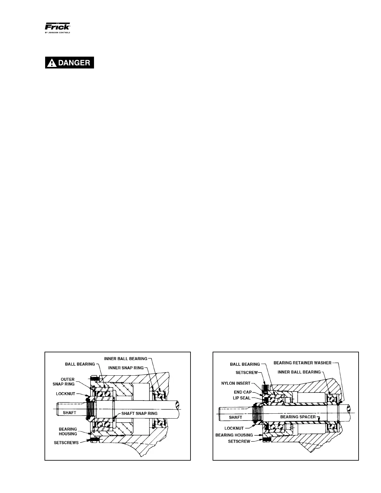
7. GG, HJ, HL: Remove snap ring from shaft. See Figure 30.
AS, AK, AL: Remove bearing spacer from shaft. See Figure
31.
8. Remove brass bar or piece of hardwood from port open
ing.
9. The rotor and shaft can now be removed by tapping on
end of shaft with a lead hammer or, if using a regular ham
mer, use a piece of hardwood between shaft and hammer.
The rotary member of the seal will come out with rotor
and shaft.
10. AS, AK, AL: Remove bearing retainer washer. The washer
may have stayed with rotor and shaft when removed or is
against ball bearing. See Figure 31.
11. Remove the mechanical seal rotary member and spring
from rotor and shaft assembly.
12. GG, HJ, HL: Remove inner snap ring and singlerow ball
bearing from casing.
AS, AK, AL: Remove singlerow ball bearing from casing.
13. Remove seal seat or stationary part of seal from casing.
14. Disassemble thrustbearing assembly.
GG, HJ, HL: Remove outer snap ring from bearing hous ing
and remove ball bearing. See Figure 30.
AS, AK, AL: Loosen two set screws in ange outside diameter.
Rotate end cap and lip seal counterclockwise and remove.
Remove ball bearing. See Figure 31.
The casing should be examined for wear, particularly in the
area between ports. All parts should be checked for wear
before pump is put together.
When making major repairs, such as replacing a rotor and
shaft, it is advisable to also install a new mechanical seal,
head and idler pin, idler, and bushing. See INSTALLATION
OF CARBON-GRAPHITE BUSHINGS.
Clean all parts thoroughly and examine for wear or damage.
Check lip seals, ball bearings, bushing, and idler pin and
replace if necessary. Check all other parts for nicks, burrs,
excessive wear and replace if necessary.
Wash bearings in clean solvent. Blow out bearings with com
pressed air. Do not allow bearings to spin; turn them slowly
by hand. Spinning bearings will damage race and balls. Make
sure bearings are clean, then lubricate with refrigeration oil
and check for roughness. Roughness can be determined by
turning outer race by hand. Replace bearings if bearings
have roughness.
Be sure shaft is free from nicks, burrs and foreign particles
that might damage mechanical seal. Scratches on shaft in
seal area will provide leakage paths under mechanical seal.
Use ne emery cloth to remove scratches or sharp edges.
Figure 30 - Thrust-Bearing assembly (GG, HJ, HL) Figure 31 - Thrust-Bearing assembly (AS, AK, AL)