RWF II ROTARY SCREW COMPRESSOR UNITS
INSTALLATION
070.610-IOM (JUN 11)
Page 13
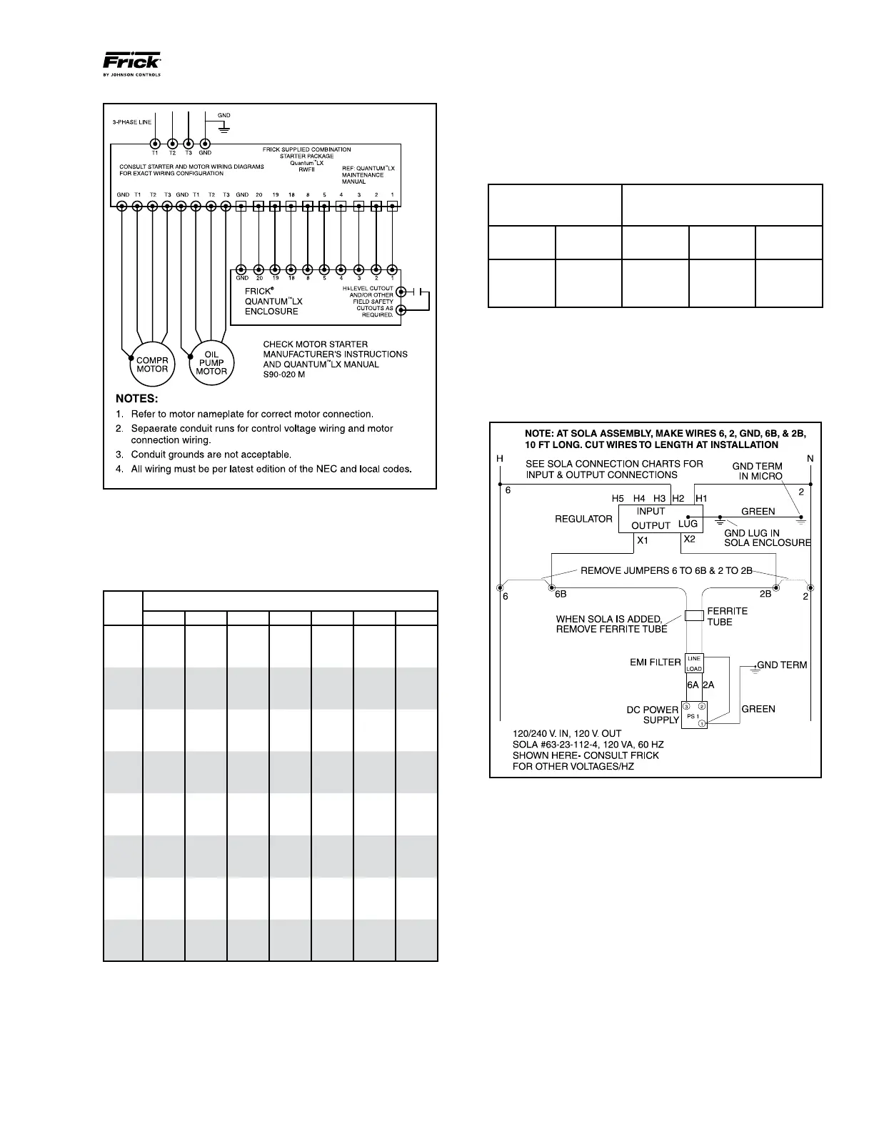
Figure 13 - Point-To-Point Wiring Diagram
CURRENT TRANSFORMER (CT) RATIOS
The CT ratio for various motor sizes (with a 5 amp second
ary) is given in the following table:
HP
VOLTAGE
200 230 380 460 575 2300 4160
20 100:5 100:5 50:5 50:5 50:5 - -
25 100:5 100:5 50:5 50:5 50:5 - -
30 200:5 100:5 100:5 50:5 50:5 - -
40 200:5 200:5 100:5 100:5 50:5 - -
50 200:5 200:5 100:5 100:5 100:5 - -
60 300:5 200:5 200:5 100:5 100:5 - -
75 300:5 300:5 200:5 200:5 100:5 - -
100 400:5 300:5 200:5 200:5 200:5 - -
125 500:5 400:5 300:5 200:5 200:5 - -
150 600:5 500:5 300:5 300:5 200:5 - -
200 800:5 600:5 400:5 300:5 300:5 100:5 50:5
250 800:5 800:5 500:5 400:5 300:5 100:5 50:5
300 1000:5 1000:5 600:5 500:5 400:5 100:5 50:5
350 - 1000:5 800:5 500:5 500:5 100:5 100:5
400 - - 800:5 600:5 500:5 200:5 100:5
450 - - 1000:5 800:5 600:5 200:5 100:5
500 - - 1000:5 800:5 600:5 200:5 100:5
600 - - 1200:5 1000:5 800:5 200:5 100:5
700 - - - 1200:5 1000:5 200:5 200:5
800 - - - - 1000:5 300:5 200:5
900 - - - - 1200:5 300:5 200:5
1000 - - - - - 300:5 200:5
1250 - - - - - 400:5 200:5
1500 - - - - - 500:5 300:5
MINI MUM BURDEN RATINGS
The following table gives the minimum CT burden ratings.
This is a function of the distance between the motor starting
package and the compressor unit.
BURDEN MAXIMUM DISTANCE FROM
RATING FRICK PANEL
ANSI VA
USING # USING # USING #
14 AWG 12 AWG 10 AWG
B-0.1 2.5 15 ft 25 ft 40 ft
B-0.2 5 35 ft 55 ft 88 ft
B-0.5 12.5 93 ft 148 ft 236 ft
CONTROL POWER REGULATOR
Compressor units that will be used in areas that suffer brown
outs and other signicant power uctuations can be supplied
with a control power regulator. See Figure 14, Recommended
Regulator Installation.
Figure 14 - Recommended Regulator Installation