RWF II ROTARY SCREW COMPRESSOR UNITS
MAINTENANCE
070.610-IOM (JUN 11)
Page 34
Be extremely careful when disman-
tling the cold-start valve on the
discharge side of the unit, as con-
densed refrigerant often is trapped between the cold-start
valve and the stop valve. A bleed valve on the side of the
check valve is used to vent the space between the check
valve and stop valve. Exposure to refrigerant fumes can
cause injury or death.
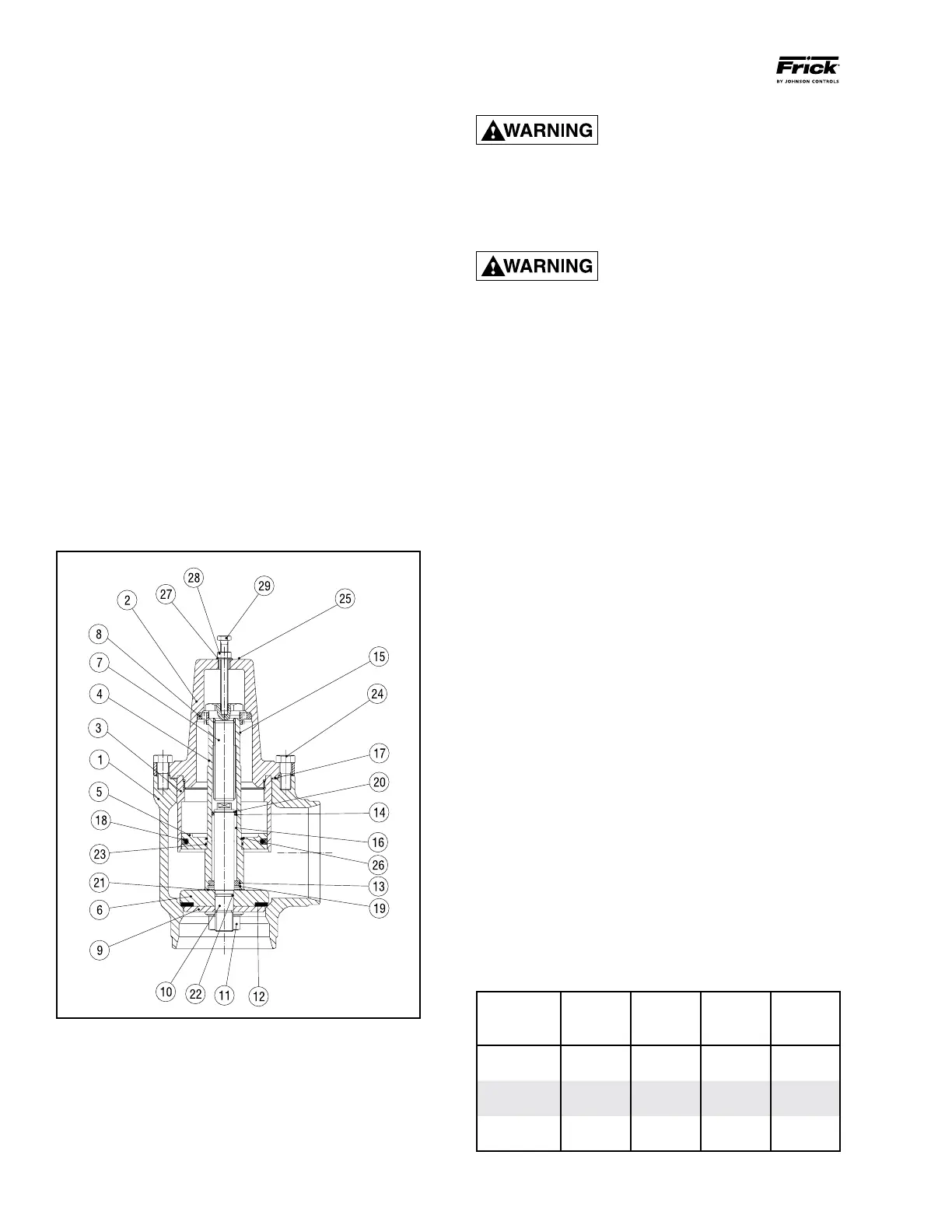
Inside the valve (see Figure 37) there
is a very heavy, tight spring (15).
Provided the valve is intact, the
spring presents no danger when dismantling. The spring
is compressed with a large bolt (7). If it is necessary to repair
the valve, it can be dismantled as follows:
1. To manually open the valve, mount the hexagon screw
(29), the hexagon ange nut (28) and the nylon ring (27) as
shown. Tighten the nut (28) a few turns, in order to redraw
the valve cone from the seat.
NOTE: Step 1 is not strictly necessary when dismantling
the valve, but will prevent the valve seat gasket from be-
ing exposed to a shear load, and it will keep all internal
valve parts together as a unit.
2. Loosen the screws (24) by 0.315 in (8 mm), and ensure
that the bonnet (2) is not under pressure from the spring.
If the bonnet is under pressure from the spring (15) after
all the screws have been loosened by 0.315 in (8 mm), there
is a damage inside the valve. In this case, it is important to
remove only two screws, one from each side.
In the threaded holes from which the two screws have been
removed, insert studs with nuts (see table for size) and
turn the nuts down to meet the bonnet (2). Studs must be
about the same length as the valve body. Then remove the
remaining two screws (24), loosen the nuts on the studs, and
carefully ease off the bonnet. All internal parts can then be
safely removed. NOTE: If step 1 was followed, loosen the
hexagon nut (28) carefully, holding the hexagon screw
(29) in place.
If the bonnet is not under pressure from the spring, all
screws (24) can be removed. The bonnet and all internal parts
can now be removed from the valve body.
When internal parts have been taken out of the valve body,
the spring can be removed by unscrewing the spring bolt (7).
NOTE: When assembling the valve, the bonnet gasket (17)
must be captured in the groove in the bonnet (2).
After the bonnet assembly is mounted into the valve housing
(1), install and tighten bonnet cap screws (24). The required
torque is shown for each valve size in the table below.
BONNET CAP SCREW TORQUE VALUES
Valve Valve Screw
Size Torque Size Torque Size
DN (mm) (Nm) ANSI (lb-ft) (mm)
65 74 2½" 54 M12
80 44 3" 32 M10
100 74 4" 54 M12
125 183 5" 134 M16
150 183 6" 134 M16
200 370 8" 271 M20
11. Incorrect refrigerant line sizing.
12. Improper system piping.
13. Problems in electrical service to compressor unit.
14. Air and moisture present in the system.
Make a list of all deviations from normal plant operation and
normal compressor unit operation. Delete any items which
do not relate to the symptom and separately list those items
that might relate to the symptom. Use the list as a guide to
further investi gate the problem.
The second step in problem solving is to decide which items
on the list are possible causes and which items are additional
symptoms. High discharge temperature and high oil tem
perature readings on a display may both be symptoms of a
problem and not casually relat ed. High suction superheat or
a low receiver level, however, could cause both symptoms.
The third step is to identify the most likely cause and take
action to correct the problem. If the symptoms are not
relieved move to the next item on the list and repeat the
procedure until you have identied the cause of the problem.
Once the cause has been identi ed and con rmed make the
necessary correc tions.
SERVICING THE COLD-START VALVE
Figure 37 - Cold-Start Valve
Before beginning to disassemble the valve, the refrigerant
must be removed from all associated piping.
Start room ventilation and put on a safety mask.