RWF II ROTARY SCREW COMPRESSOR UNITS
INSTALLATION
070.610-IOM (JUN 11)
Page 6
CHECKING MOTOR/COMPRESS OR ROTA TION
Make sure coupling hubs are tight-
ened to the shaft before rotatingthe
motor to prevent them from ying
off and possibly causing serious injury or death.
Injury may occur if loose clothing,
etc, becomes entangled on the spin-
ning motor shaft.
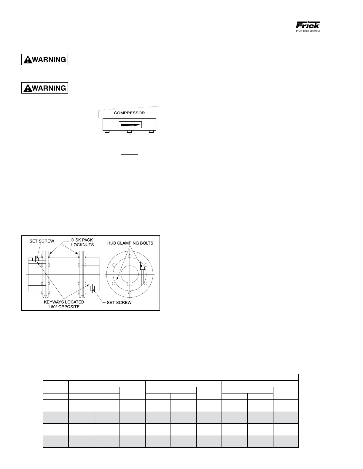
COMPRESSOR ROTATION IS
CLOCKWISE WHEN FACING
THE END OF THE COM-
PRESSOR SHAFT. Under NO
conditions should the motor
rotation be check ed with the
coupling center installed as
damage to the com pressor
may result. Bump the motor
to check for correct compressor rotation. After verication,
install disc drive spacer, as applicable.
COMPRESSOR/MOTOR COUPLING
INSTALLATION
The RWF II unit has compressor to motor alignment through
the use of a machined cast iron tunnel. This tunnel is factory
set through machining tolerances ensuring motor compres
sor alignment. No alignment is required in the eld. See
Figure 1.
BP COUPLING INSTALLATION PROCEDURE
Figure 1 - BP Coupling
1. Install the motor and compressor coupling hubs and keys
on their respective shafts. Ensure that they can slide hori
zontally so that once the disc packs are installed, no axial
stress is transferred to the disc packs by a stuck coupling
hub. Use no lubricants.
2. Rotate both hubs so that the keys are 180° opposed.
With the hubs mounted and the axial spacing set, proceed to
BP SERIES COUPLING DATA TABLE
BP
DISC PACK LOCKNUT HUB CLAMPING BOLTS KEYWAY SETSCREW
SERIES
TORQUE (Lube*)
SIZE UNF
TORQUE
SIZE UNF
TORQUE
SIZE NC
SIZE FT-LB NM FT-LB NM FT-LB NM
BP 43 40 54.2 7/16-20 49 66.4 3/8-24 10 13.6 3/8-16
BP 48 40 54.2 7/16-20 49 66.4 3/8-24 20 27.1 1/2-13
BP 53 60 81.4 1/2-20 78 105.8 7/16-20 20 27.1 1/2-13
BP 58 120 162.7 5/8-18 120 162.7 1/2-20 20 27.1 1/2-13
BPU-38* 22 30 5/16-24 N/A N/A N/A 22 30 3/8-16
BPU-41* 55 75 7/16-20 N/A N/A N/A 22 30 3/8-16
BPU-47* 120 162.7 9/16-18 N/A N/A N/A 50 68 1/2-13
BPU-54* 120 162.7 9/16-18 N/A N/A N/A 50 68 1/2-13
place the spacer between the two hub anges. Care should
be taken when handling the spacer. Be sure the spacer is
fully supported at this time. Damage to the unitized ex discs
may result after they have been installed if the spacer is not
fully supported.
Install the unitized ex disc at this time. Start a bolt through
a bolt hole in the spacer. Put the unitized ex disc between
the hub and spacer until a bushing hole in the unitized ex
disc lines up with the bolt. Slide the bolt through the bushing
hole in the unitized ex disc. Install the locknut until it is snug.
Make sure that all bolt threads are clean and lightly oiled. Do
not torque any locknuts at this time. Now pivot the unitized
ex disc until the other bushing holes in the ex disc are in
line with the bolt holes in the spacer. Install the rest of the
spacer bolts at this time. The remaining bolts for this end of
the coupling can be installed through the hub bolt holes and
ex disc bushing holes.
Install the unitized ex disc in the other end of the coupling.
The unitized ex disc, as installed, should look at and parallel
with the mating hub and spacer anges.
Torque the disc pack locknuts as recommended in the BP
COUPLING DATA TABLE. The bolts should be held in place
while the locknuts are torqued.
3. Center the coupling between the shafts. Ensure that the
keys are fully engaged in their keyways.
4. Tighten the motor and compressor shaft clamping bolts
evenly. Torque to the recommended specication in the BP
coupling data table.
5. Torque the keyway setscrews as recommended in the BP
COUPLING DATA TABLE.
IMPORTANT: Only after the shaft clamping bolts are tight-
ened to their nal torque can the keyway set screws be
tightened. If the keyway set screws are tightened before
the shaft clamping bolts are tightened, then the hubs can
be cocked on the shaft.
CH COUPLING INSTALLATION PROCEDURE
The T. B. Woods Elastomeric Type CH Coupling is used in
most applications. This coupling consists of two drive hubs
and a geartype Hytrel or EDPM and neoprene drive spacer.
The split hub is clamped to the shaft by tightening the clamp
screws. Torque is transmitted from the motor through the
elastomeric gear which oats freely between the hubs. Be
cause of the use of the motor/compressor adapter housing
on the RWF II, no eld alignment is necessary.
1. Inspect the shaft of the motor and compressor to ensure
that no nicks, grease, or foreign matter is present.
2. Inspect the bores in the coupling hubs to make sure that
they are free of burrs, dirt, and grit.