RWF II ROTARY SCREW COMPRESSOR UNITS
INSTALLATION
070.610-IOM (JUN 11)
Page 10
ECONOMIZER - HIGH STAGE (OPTIONAL)
The economizer option provides an increase in system capac
ity and efciency by subcooling liquid from the condenser
through a heat exchanger or ash tank before it goes to the
evapora tor. The subcooling is provided by ashing liquid in
the economizer cooler to an intermediate pressure level. The
intermediate pressure is provided by a port located part way
down the compres sion process on the screw compressor.
As the screw compressor unloads, the economizer port will
drop in pressure level, eventually being fully open to suc
tion. Because of this, an output from the microproces sor is
generally used to turn off the supply of ashing liquid on a
shell and coil or DX economizer when the capacity falls be
low approximately 60%70% capacity (85%90% slide valve
position). This is done because the compressor will be more
efcient operating at a higher slide valve position with the
economizer turned off, than it will at a low slide valve posi
tion with the economizer turned on. Please note however
that shell and coil and DX economizers can be used at low
compressor capaciti es in cases where efcien cy is not as
important as assuring that the liquid supply is subcooled. In
such cases, the economi zer liquid solenoid can be left open
whenever the com pressor is running.
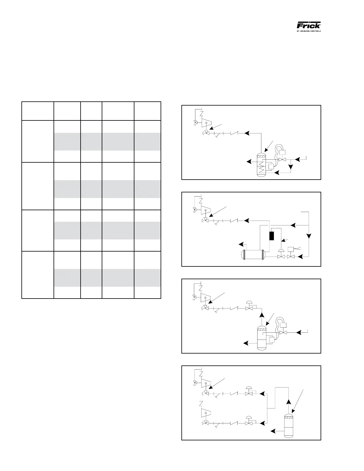
Due to the tendency of the port pressure to fall with de creasing
compressor capacity, a backpressure regulator valve (BPR) is
generally required on a ash economizer system (Figure 10) in
order to maintain some preset pressure dif ference between
the subcooled liquid in the ash vessel and the evaporato rs.
Figure 9 - Direct Expansion Economizer System
Figure 8 - Shell and Coil Economizer System
Figure 11 - Multiple Compressor Economizer System
Figure 10 - Flash Economizer System
HIGH
PRESSURE
LIQUID
INTERMEDIATE PRESSURE
GAS TO COMPRESSOR
SUCTION
STR
VCK
SUBCOOLED
HIGH PRESSURE
LIQUID TO
EVAPORATOR
ECONOMIZER
COOLER
ECON1
HV-2
HIGH
PRESSURE
LIQUID
INTERMEDIATE PRESSURE
GAS TO COMPRESSOR
SUCTION
STR
VCK
SUBCOOLED
HIGH PRESSURE
LIQUID TO
EVAPORATOR
ECONOMIZER
COOLER
WIRING
ECON2
HV-2
HIGH
PRESSURE
LIQUID
INTERMEDIATE PRESSURE
GAS TO COMPRESSOR
SUCTION
STR
VCK
CONTROLLED
PRESSURE
SATURATED LIQUID
TO EVAPORATOR
ECONOMIZER
VESSEL
BPR
ECON3
HV-2
INTERMEDIATE PRESSURE
GAS TO COMPRESSOR
SUCTION
STR VCK BPR
CONTROLLED PRESSURE
SATURATED LIQUID TO EVAPORATOR
ECONOMIZER
VESSEL
ECON4
HV-2
your local distributor, but they must be suitable for stainless
steel. The oil cooler may be cleaned in place by back ushing
with recommended solution for approximately 30 minutes.
After back ushing, rinse the heat exchanger with fresh water
to remove any remaining cleaning solution.
TABLE 1 - LIQUID LINE SIZE and RECEIVER VOLUME
CONDITIONS: Booster: 40°F Evap, 95°F Cond and 10°F
Intermediate; HI Stage: 0°F Evap, and 95°F Cond
PIPING
LINE
SIZE
POUND
PER MIN.
PER 5 MIN.
LIQUID
VOLUME
CU FT
REFRIG
RWF II
MODEL
R-717
High Stage*
100-134 1½ 81.0 2.2
177-270 2 132.0 3.6
316-480 3 236.5 6.4
496 3 305.0 8.3
546 3 323.5 8.8
676 4 417.0 11.4
856 4 532.0 14.5
R-717
Booster*
100-134 3/4 11.5 0.3
177-270 1¼ 17.0 0.4
316-480 1½ 31.0 0.8
496 1½ 38.5 0.9
546 1½ 42.5 1.0
676 2 54.0 1.3
856 2 69.5 1.7
1080 2 91.5 2.2
R-507
High Stage*
100-134 1¼ 229.0 3.7
177-270 2 370.5 6.0
316-480 2 664.0 10.7
496 2½ 878.5 14.1
546 2½ 908.5 14.6
676 3 1200.0 19.3
856 3 1243.0 20.0
R-507
Booster*
100-134 1/2 28.5 0.5
177-270 1/2 38.5 0.6
316-480 3/4 69.0 1.1
496 1 103.0 1.7
546 1 94.5 1.5
676 1¼ 141.5 2.3
856 1¼ 160.0 2.6
1080 2 336.0 5.4
* Based on 100 foot liquid line. For longer runs, increase line
size accordingly.