RWF II ROTARY SCREW COMPRESSOR UNITS
MAINTENANCE
070.610-IOM (JUN 11)
Page 28
DEMAND PUMP ASSEMBLY
Assembly Notes On Standard Mechanical Seal (Synthetic
Rubber Bellows Type)
NOTE: Read carefully before reassembling pump
The seal used in this pump is simple to install and good
performance will result if care is taken during installation.
The principle of mechanical seal is contact between the
rotary and stationary members. These parts are lapped to
a high nish and their sealing effectiveness depends on
complete contact.
Prior to installing rotary portion of mechanical seal, prepare
and organize rotor shaft, head and idler assemblies and ap
propriate gaskets for quick assembly
Once rotary portion of mechanical seal is installed on rotor
shaft, it is necessary to assemble parts as quickly as pos
sible to ensure that the seal does not stick to shaft in wrong
axial position. The seal will stick to the shaft after several
minutes setting time.
Never touch sealing faces with anything except clean hands
or clean cloth. Minute particles can scratch the seal faces
and cause leakage.
1. Coat idler pin with refrigeration oil and place idler and
bushing on idler pin in head. If replacing a carbongraphite
bushing, refer to "Installation of Carbon Graphite Bushings".
2. Clean rotor hub and casing seal housing bore. Make sure
both are free from dirt and grit. Coat outer diameter of seal
seat and inner diameter of seal housing bore with refrigera
tion oil.
3. Start seal seat in seal housing bore. If force is necessary,
protect seal face with a clean cardboard disc and gently tap it
in place with a piece of wood. Be sure seal seat is completely
seated in the bore.
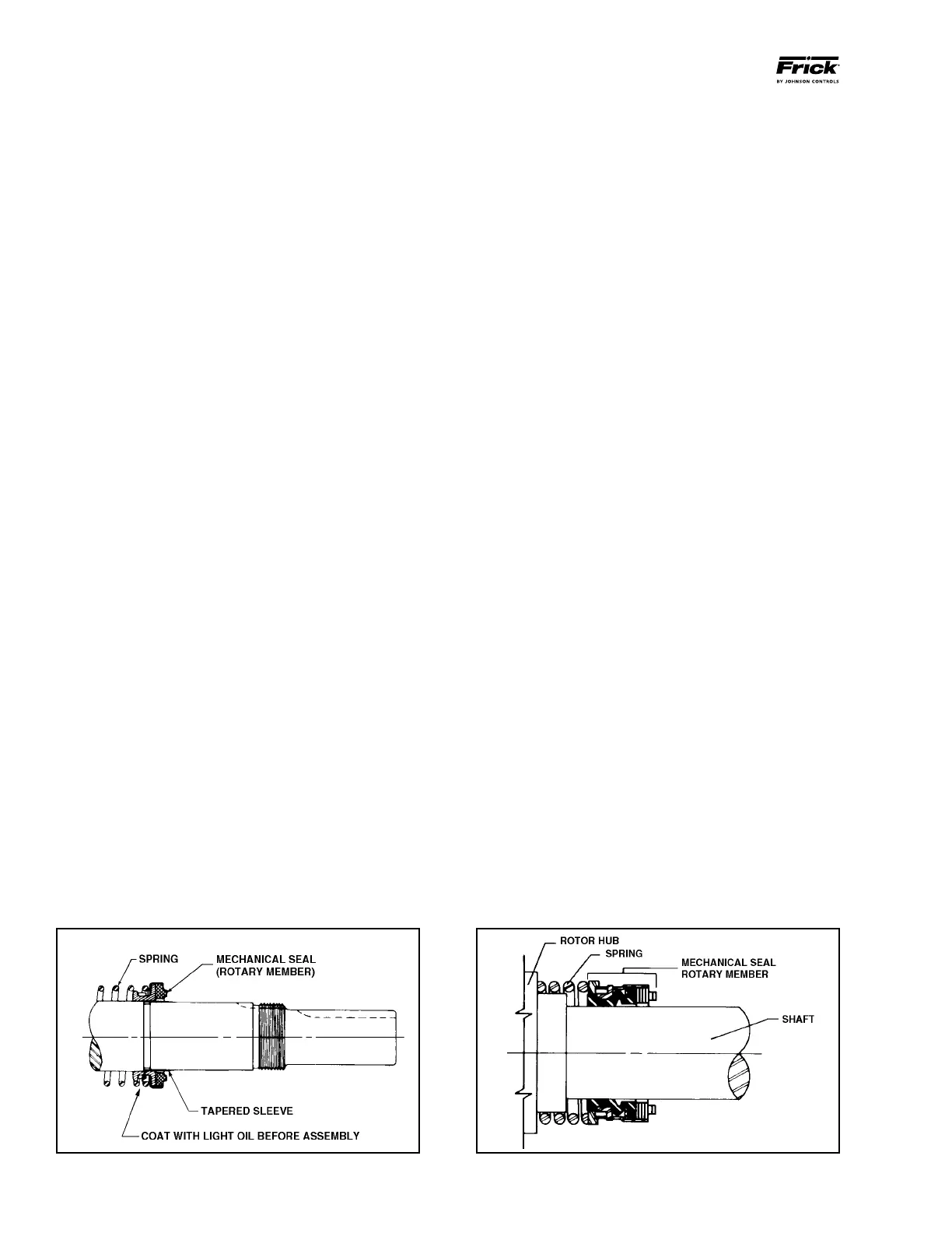
4. Place tapered installation sleeve on shaft. Refer to Figure
32. Sleeve is furnished with GG, AS, AK, and AL replacement
mechanical seals. Coat rotor shaft, tapered installation sleeve,
and inner diameter of mechanical seal rotary mem ber with
a generous amount of refrigeration oil. Petrolatum may be
used but grease is not recommended.
5. Place seal spring on shaft against rotor hub. Refer to
Figure 33.
6. Slide rotary member, with lapped contact surface fac
ing away from spring, over installation sleeve on shaft until
just con tacting the spring. Do not compress spring. Remove
installa tion sleeve.
7. Coat rotor shaft with refrigeration oil. Install shaft slowly
pushing until the ends of rotor teeth are just below the face
of the casing.
8. Leave the rotor in this position. Withdrawal of rotor and
shaft may displace the carbon seal rotating face and result
in damage to the seal.
9. Place Oring gasket on head and install head and idler
assembly on pump. Pump head and casing were marked
before disassembly to ensure proper reassembly. If not, be
sure idler pin, which is offset in pump head, is positioned up
and equal distance between port connections to allow for
proper ow of liquid through pump.
10. Tighten head capscrews evenly
11. Pack inner ball bearing with multipurpose grease, NLGI
#2.
GG, HJ, HL: Install bearing in casing with sealed side towards
head end of pump. Drive the bearing into the bore. Tap the
inner race with a brass bar and lead hammer to position
bearing. Install inner snap ring.
AS, AK, AL: Install bearing retainer washer over the shaft
before installing ball bearing. Install ball bear ing in casing with
sealed side towards head end of pump. Drive the bearing
into the bore. Tap the inner race with a brass bar and lead
hammer to position bearing.
12. GG, HJ, HL: Install shaft snap ring in groove in the shaft.
See Figure 30.
AS, AK, AL: Install bearing spacer over shaft and against
single row ball bearing. See Figure 31.
13. Pack lubrication chamber between inner ball bearing and
doublerow ball bearing in the thrustbearing assembly ap
proximately onehalf full of multipurpose grease, NLGI #2.
The thrustbearing assembly will take the remaining space.
See Figure 30 and 31.
14. Pack doublerow ball bearing with multipurpose grease,
NLGI #2.
GG, HJ, HL: Install ball bearing into bearing housing with
shield side toward coupling end of shaft. See Figure 30. Install
snap ring into bearing hous ing to retain ball bearing. This
snap ring has a tapered edge to t tapered groove in bearing
housing. The tapered edge is located away from ball bearing.
Figure 32
Figure 33