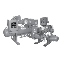
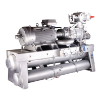
RXF ROTARY SCREW COMPRESSOR UNITS
OPERATION
070.410-IOM (JAN 12)
Page 19
• Alarms
- If an alarm has been detected the ICAD display (Figure
23) will alternate between showing Actual alarm and
present Opening Degree.
- If more than one alarm is active at the same time, the
alarm with the highest priority will take preference. A1
has the highest priority, A3 the lowest.
- All alarms will automatically reset themselves when they
physically disappear.
- Old alarms (alarms that have been active, but have
physically disappeared again) can be found in parameter
i11.
Typically motorized valves are factory set. If adjustments are
needed, the following procedure can be used.
1. Ensure that there is power to the valve (24 VDC) and all
wiring is complete prior to conguring the motorized valve.
The ICAD 600 requires 1.2 amps for operation and the ICAD
900 requires 2.0 amps.
2. Identify which actuator is being used (ICAD 600 or 900)
and which motorized valve is being used (ICM 20, 25, 32, 40,
50, or 65). Ensure that the correct actuator is being used
with the ICM valve as follows:
ICM20 with ICAD 600
ICM25 with ICAD 600
ICM32 with ICAD 600
ICM40 with ICAD 900
ICM50 with ICAD 900
ICM65 with ICAD 900
3. When the valve is initially powered, A1 and CA will be
ashing on the LED display. Hold the enter button down for
two seconds until these values stop ashing.
4. Push the down arrow button and scroll until j10 is displayed
and push the enter button. Using the up arrow, scroll until
j11 is displayed and push the enter button. This step must be
completed within 20 seconds or the valve will reset.
5. Push the down arrow button again and scroll until j26 is
displayed and push the enter button. Identify the ICM valve
being used and push the up arrow until the correct number is
displayed for the ICM valve and then push the enter button.
The values are as follows:
1 for ICM20
2 for ICM25
3 for ICM32
4 for ICM40
5 for ICM50
6 for ICM65
6. The ICAD will store these parameters with the power
removed.
Alarms - ICAD can handle and display different alarms.
Description
ICM
Alarm Text
Comments
No valve type
selected
A1 At start-up A1 and CA will be
displayed
Controller fault A2 Internal fault inside electronics
All input error A3 When input amps are > 22 mA
Reset to factory setting:
1. Remove the power supply.
2. Activate down arrow and up arrow push buttons at the
same time.
3. While continuing to push the down and up arrows, con-
nect the power supply.
4. Release down arrow and up arrow push buttons.
5. When the display on ICAD (Figure 23) is alternating
between showing: CA and A1 the factory resetting is
complete.

 Loading...


