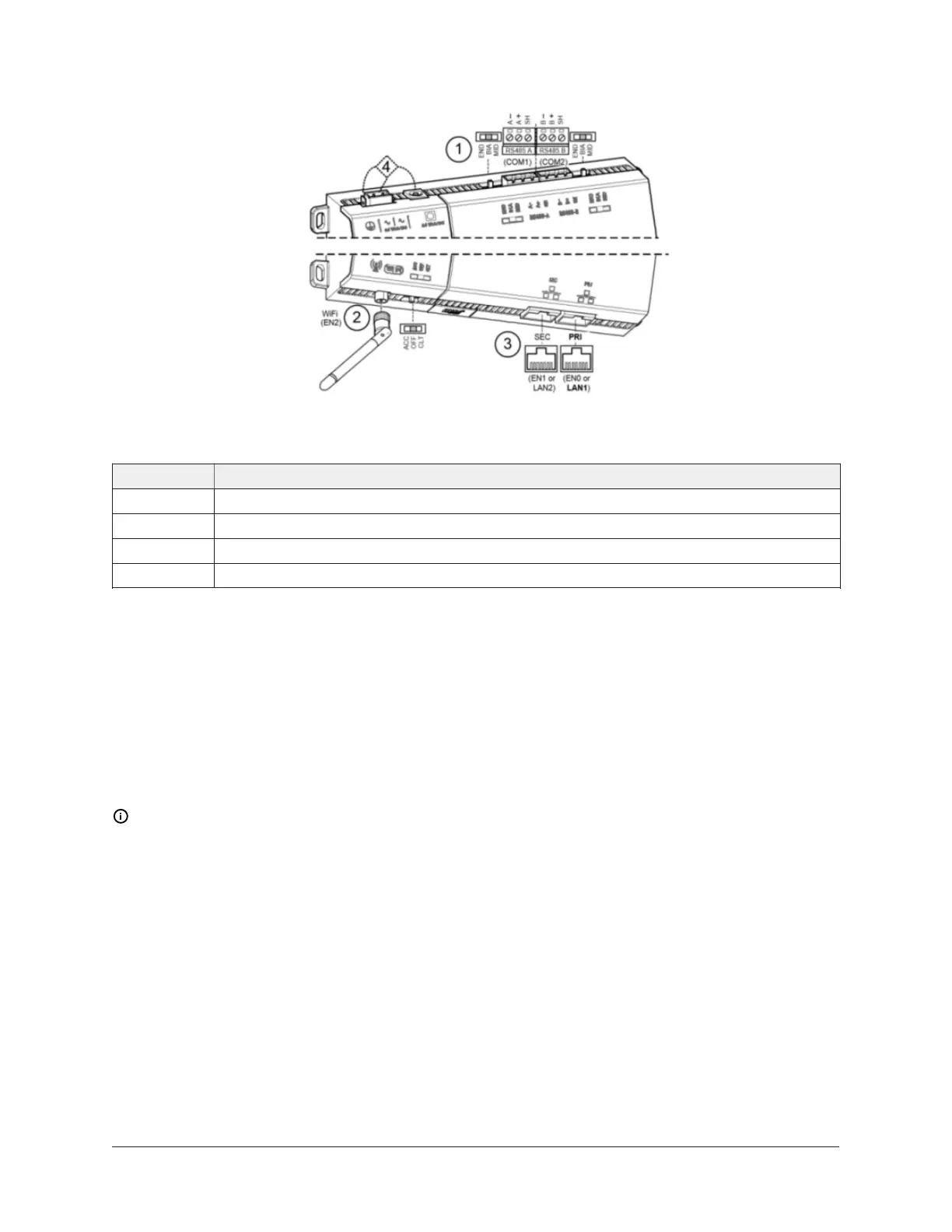
Figure 6: Communications ports on the Controller
Table 1: Communications ports on the Controller
Callout Description
1 RS-485 ports and bias switches
2 Wi-Fi adapter, settings switch, and antenna
3 Ethernet ports, 10/100-Mbit, RJ-45
4 Earth ground and 24 V power input
Wi-Fi
An integral Wi-Fi adapter provides wireless connectivity using the IEEE 802.11b/g/n standard, and
provides an RP-SMA coax antenna connector.
The Wi-Fi configuration switch sets operation as follows:
• OFF - (Default, middle) Wi-Fi adapter is disabled.
• ACC - Controller provides operation as a Wi-Fi access point for up to 20 clients.
• CLT - Controller operates as a client to an existing 802.11b/g/n router or access point.
Note: By default, the Wi-Fi software is disabled. You must enable the WiFi within the software
before it becomes available.
RS-485 wiring
On the controller's top side, two RS-485 ports operate as COM1 and COM2. Each port is capable of
up to 115,200 baud, and uses a 3-position, screw terminal connector.
Use shielded, twisted-pair, 18-22 AWG cabling to wire in a continuous daisy chain fashion to other
RS-485 devices: minus-to-minus, plus-to-plus, and shield-to-shield. Connect the shield wire to earth
ground at one end only.
For more information about wiring guidelines, refer to FX-PC Series Controllers MS/TP
Communications Bus Technical Bulletin (LIT-12011670).
7FX80 Supervisory Controller Installation Instructions