SM-18003
3-7
TROUBLESHOOTING
3.1.3 Checking Rotary Switch and DIP Switch Settings
The following diagram indicates the factory settings of DSWs on PCBs in the indoor and outdoor units.
When simultaneous operation control of multiple units or room thermo control is operated, the DSW setting
will be different as shown below.
(1) Outdoor Unit (Factory Setting)
Refer to the Service Manual for Outdoor Unit.
● Mini Cassette
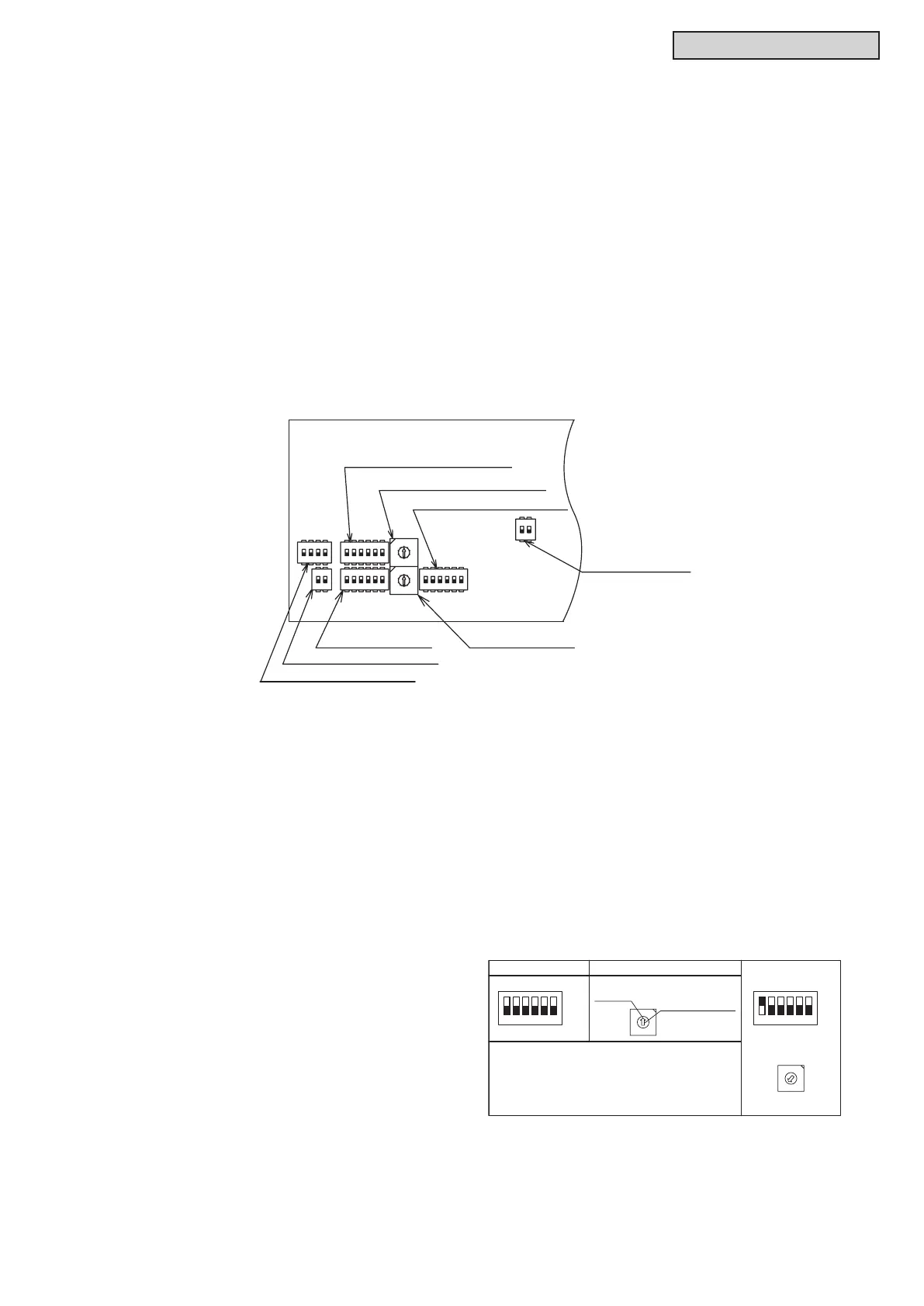
(2) Indoor Unit (Factory Setting)
The positions of the DIP switches on the PCB are shown in the gure below. Turn OFF all power
sources before setting.
Without turning OFF all power sources, the switches do not work and the settings are invalid.
The “
n
” mark indicates the position of DIP switches.
1 2 3 4 5 6
ON
OFF
1 2 3 4 5 6
ON
OFF
DSW6 (Tens Digit)
RSW1 (Units Digit)
Setting
Position
Set by inserting
slotted screwdriver
into the groove.
Ex.) Set at No.16 Unit
DSW6
RSW1
Set No.1 Pin at ON side
Set at "6"
3
4
1
0
8
9
2
5
6
7
3
4
1
0
8
9
2
5
6
7
Factory settings for DSW6 and RSW1 are set at "0".
For the units supporting H-LINK II, the unit numbers can
be set for a maximum of 64 indoor units (No.0 to 63).
DIP Switch Settings
(1) Turn OFF the power supply of the indoor unit and the outdoor unit before DIP switch setting. Not doing
so makes the setting invalid.
(2) Factory settings for DSW6 and RSW1 are set to “0”. If connecting the indoor unit to H-LINK II
supporting the outdoor unit without setting any DIP switches, auto-address setting will be performed by
the wired controller.
(3) Auto-Address Setting by Wired Controller
The address numbering is started from “0” by the auto-address function when the wired controller is
connected to H-LINK II.
(4) Unit No. Setting (RSW1 and DSW6)
The indoor unit numbers of all indoor units
are not required. The indoor unit numbers
are set by the auto-address function. If the
indoor unit number setting is required, set the
unit numbers of all indoor units respectively
and serially by following setting positions. It
is recommended to assign a number to each
indoor unit beginning with “1.” Though a
maximum of 64 indoor units per refrigerant
system can be connected to the H-LINK ll
System, available numbers range from 0 to 63.
Therefore, the applicable number for the 64th
indoor unit will be “0.”
For centralized control, this setting is required.
0
9
8
7
6
5
4
3
2
1
0
9
8
7
6
5
4
3
2
1
DSW5 (Refrigerant Cycle No. Setting)
RSW2 (Refrigerant Cycle No. Setting)
DSW3 (Capacity Code No. Setting)
DSW4 (Unit Model Code Setting)
DSW9 (Optional Function Setting)
DSW6
(Indoor Unit No. Setting)
RSW1
(Indoor Unit No. Setting)
DSW4 DSW5
RSW2
DSW9 DSW6
RSW1
DSW3
DSW7
ON
ON
ON
ON
ON
ON
1234 56
1 234 56
123456
1 2
1 234
1 2

 Loading...