5-6
SM-18003
EXTERNAL INPUT/OUTPUT AND FUNCTION SETTING
5.4.1.1 RemoteControlON/OFFFunction
Thisfunctionprovidesacontroltostopandstartthesystemautomaticallyfromaremoteplace.Four
methodsareavailablebyusingeachsignalfromabuildingmanagementsystem.
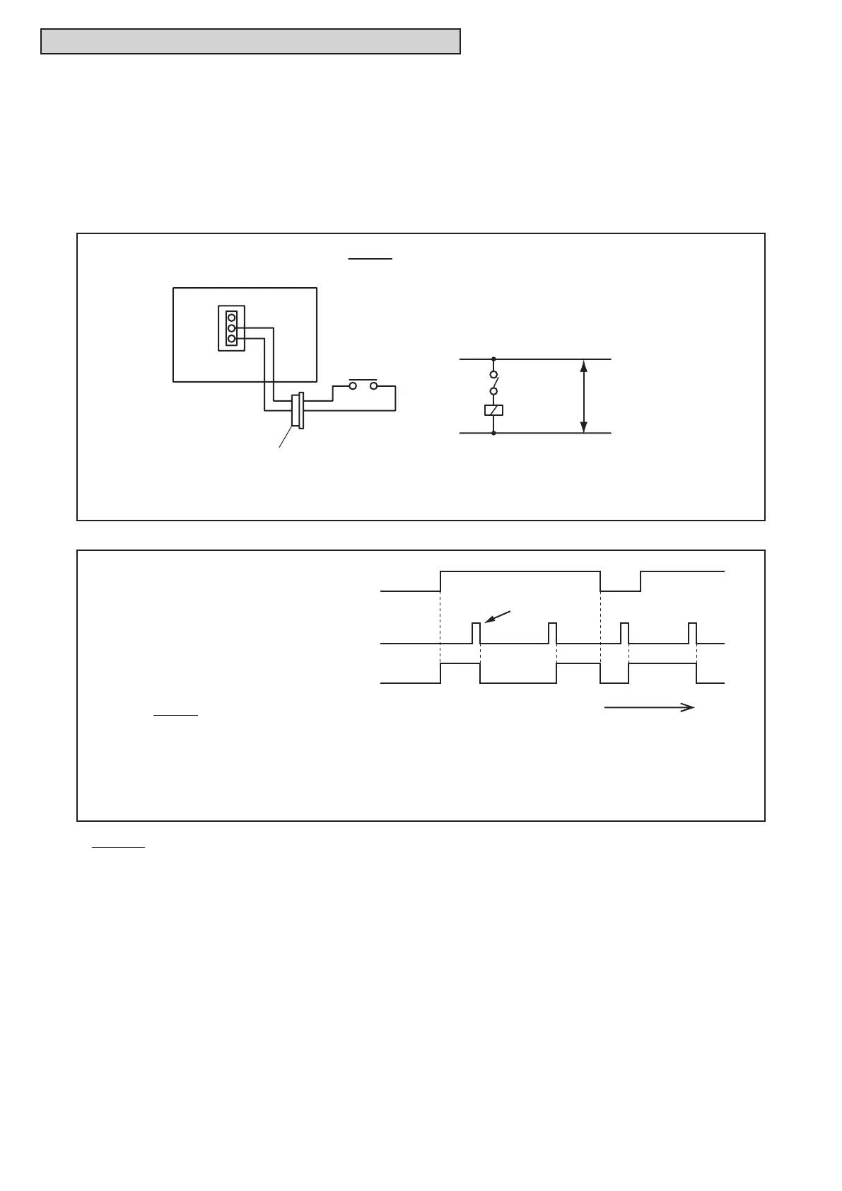
(1) RemoteON/OFF1(LevelSignalInput)[InputSetting:Code(03)]
ThisisanON/OFFfunctionfromaremoteplacebyusinglevelsignals(ON/OFF).Anexampleof
basicwiringandtimechartisshownbelow.
NOTES:
1.Pickingupsignalwithin10secondsafterpowersupplyisturnedONisnotpossibleduetoinitializationof
thecomponents.
Donotchangethesignal(ON/OFF)inthisperiod.
2.WiredControllerisrequiredforthisfunction.
3.Ifmultipleindoorunitsareconnectedtothesamecommunicationcableforwiredcontroller,inputthe
signaltoanyoftheseindoorunits.
4.Whenthecommunicationcableisnotusedinthetwin,tripleandquadcombinationsforsimultaneous
operation,inputthesignaltothemainindoorunit.
SS3
X1
Power
Source
Control Circuit
Indoor Unit PCB
CN3
X1
3P Connector
3
2
1
2
1
NOTE:
When the unit is started by the remote ON/OFF switch,
the fan speed is subject to the mode memorized in
the wired controller.
SS3: Remote ON/OFF
Wiring Diagram Example of Remote ON/OFF
(Example: Remote ON/OFF is set to terminals 1 and 2 of CN3)
ON
OFF
ON
OFF
Ti
Unit Operation
Signal to terminals 1 & 2 of CN3
Control by Wired Controller
Press the ON/OFF switch.
Time Chart
NOTE:
Operation priority is given to the remote
ON/OFF signal or wired controller
signal which is given last.
(Example: Remote ON/OFF is set to terminal 1 and 2 of CN3)

 Loading...