6-6
SM-18003
FIELD WORK INSTRUCTIONS
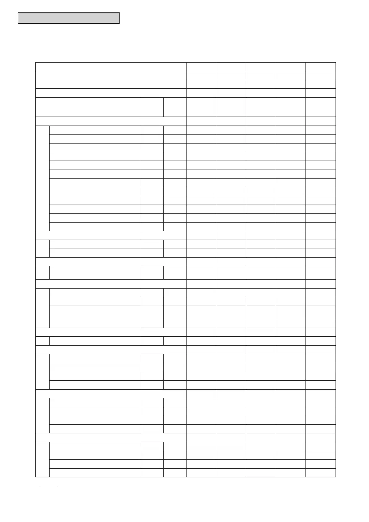
6.5 Service and Maintenance Record by Wired Controller
Data Sheet for Checking by Wired Controller
Time : : : : :
I.U. Model
I.U. Serial No.
I.U. No. / Alarm Code
Check
Mode
1
Check
Mode
2
1 • 2 1 • 2 1 • 2 1 • 2 1 • 2
B Temp. Indication
Set Temp. b1 - -
Inlet Air Temp. b2 q1
Discharge Air Temp. b3 q2
Liquid Pipe Temp. b4 q3
Remote Thermistor Temp. b5 - -
Outdoor Air Temp. b6 q4
Gas Pipe Temp. b7 q5
Evaporating Temp. at Heating b8 q6
Condensing Temp. at Cooling b9 q7
Comp. Top Temp. bA q8
Thermo Temp. of Wired Controller bb - -
Not Prepared bC - -
C Micro-Computer State Indication
I.U. Micro-Computer C1 - -
O.U. Micro-Computer C2 - -
D Stopping Cause State Indication
Cause Code of
Indoor Unit Stoppage
d1 - -
E Alarm Occurrence
Times of Abnormality E1 - -
Times of Power Failure E2 - -
Times of
Abnormal Communication
E3 - -
Times of Inverter Tripping E4 - -
F Automatic Louver State
Louver Sensor State F1 - -
H Pressure, Frequency State Indication
Discharge Pressure H1 q9
Suction Pressure H2 qA
Control Information H3 qb
Operating Frequency H4 qC
J I.U. Capacity Indication
I.U. Capacity J1 - -
O.U. Code J2 - -
Refrigerant System Number J3 - -
Refrigerant System Number J4 - -
L Opening of Expansion Valve
I.U. Expansion Valve L1 qd
O.U. Expansion Valve 1 L2 qE
O.U. Expansion Valve 2 L3 - -
O.U. Expansion Valve B L4 - -
NOTE:
Refer to Section 3.1.4 “Checking Wired Controller” for items of check mode.

 Loading...