SM-18003
5-13
EXTERNAL INPUT/OUTPUT AND FUNCTION SETTING
NOTES:
1.WiredControllerisrequiredforthisfunction.
2.RefertoTable5.1fordetailsoftherequiredcomponents.
3.Ifmultipleindoorunitsareconnectedtothesamecommunicationcableforwiredcontroller,inputthe
signaltoanyoftheseindoorunits.
4.Whenthecommunicationcableisnotusedinthetwin,tripleandquadcombinationsforsimultaneous
operation,setthisfunctiononlytothemainindoorunit.
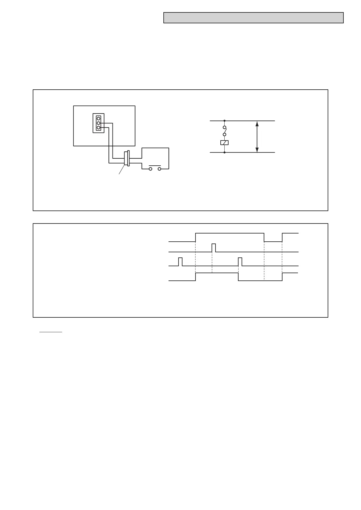
Wiring Diagram Example
(Example: Remote Cooling/Heating Change is set to terminals 1 and 2 of CN3.)
CN3
X1
3P Connector
3
2
1
2
1
COOLHEAT
X1
Power
Source
Signal to terminals 1 & 2 of CN3
Heat
Cool
Heat
Cool
Operation Mode of Unit
Control by Wired Controller (Cool)
Time Chart
(Example: Remote Cooling/Heating Change is set to terminals 1 and 2 of CN3.)
Control by Wired Controller (Heat)
5.4.1.5 RemoteCooling/HeatingChange[InputSetting:Code(07)]
Thecoolingorheatingoperationmodecanbechangedbygivingacontactsignalfromtheoutsidetothe
unit.SetthisfunctiontoCN3withawiredcontrolleraccordingtoSection5.4.2.1“FunctionSelectionItem.”
ThisfunctiondetectsONtoOFFtransitionandOFFtoONtransition.Ofthecommandsbythissignaland
awiredcontroller,thecommandgivenlaterispreferentiallyexecuted.Anexampleofbasicwiringandtime
chartisshownbelow.

 Loading...