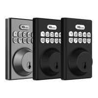
Installing the IQ Lock-PG
The diagram shows you how to install the IQ Lock-PG components.
Figure 4: IQ Lock-PG installation overview
Callout Component
A Physical key X 2
B Exterior assembly
C Latch
D Latch screws
E Strike screws
F Strike and optional reinforcement plate
G Mounting plate
H Screws for mounting the interior assembly to the door. Door thickness should
be between 35 mm and 58 mm.
I Interior assembly
J Screws
K Battery cover
Choosing a faceplate
The IQ Lock-PG latch has a rectangular faceplate in place as the default faceplate. A round drive-in
collar is included in the kit if it is required. The following topics outline how to choose the correct
faceplate:
• Checking the rectangular faceplate
• Attaching the round drive-in collar
IQ Lock-PowerG Installation and User Guide D-30924010

 Loading...