When a relay output is on, observe the following settings:
• Corresponding green LED on the module housing lights
• L.C. to L.N.O. relay contact closes. The line is normally open.
• L.C to L.N.C. relay contact opens. The line is normally closed.
• Corresponding output status screen in the UI displays On
When a relay output is off, observe the following settings:
• Corresponding green LED on the module housing does not light
• L.C. to L.N.O. relay contact opens
• L.C. to L.N.C. relay contact closes
• Corresponding output status screen in the UI displays OFF
Order condensing unit control modules and expansion modules with one or two relay outputs. For
more information about the System 450 series modules, see Ordering information and Related
documentation.
Reverse relay control logic: The state of the equipment load is normally directly related to the
state of the LED or the output status that is displayed on the user interface. For example, if the
status of the LED is ON, the output relay coil energizes and the status of the load is ON. There
are some loads that require reverse control logic. This means that when the status of the LED is
ON and/or the display status is ON, the relay coil actually de-energizes and the load is ON. In the
C450CCU, you can choose one of the following options to configure the behavior of each output
relay as related to the displayed status of the output:
• Energize the relay coil when the displayed status of the output is ON.
• Energize the relay coil when the displayed status of the output is OFF.
This parameter operates in conjunction with how the controlled equipment is wired through the
associated relay contacts, N.O. or N.C., to provide a known fail safe state in the event of controller
failure or loss of power.
Relay outputs for a fail-safe state
In the event of controller failure, use the NRGZ parameter in the ModE menu to provide a fail-safe
state, based on how the refrigeration equipment is wired to the various C450 relays. For more
information, see Figure 2. Use the following table for information on how to achieve the desired
fail-safe state for any of the CCU outputs.
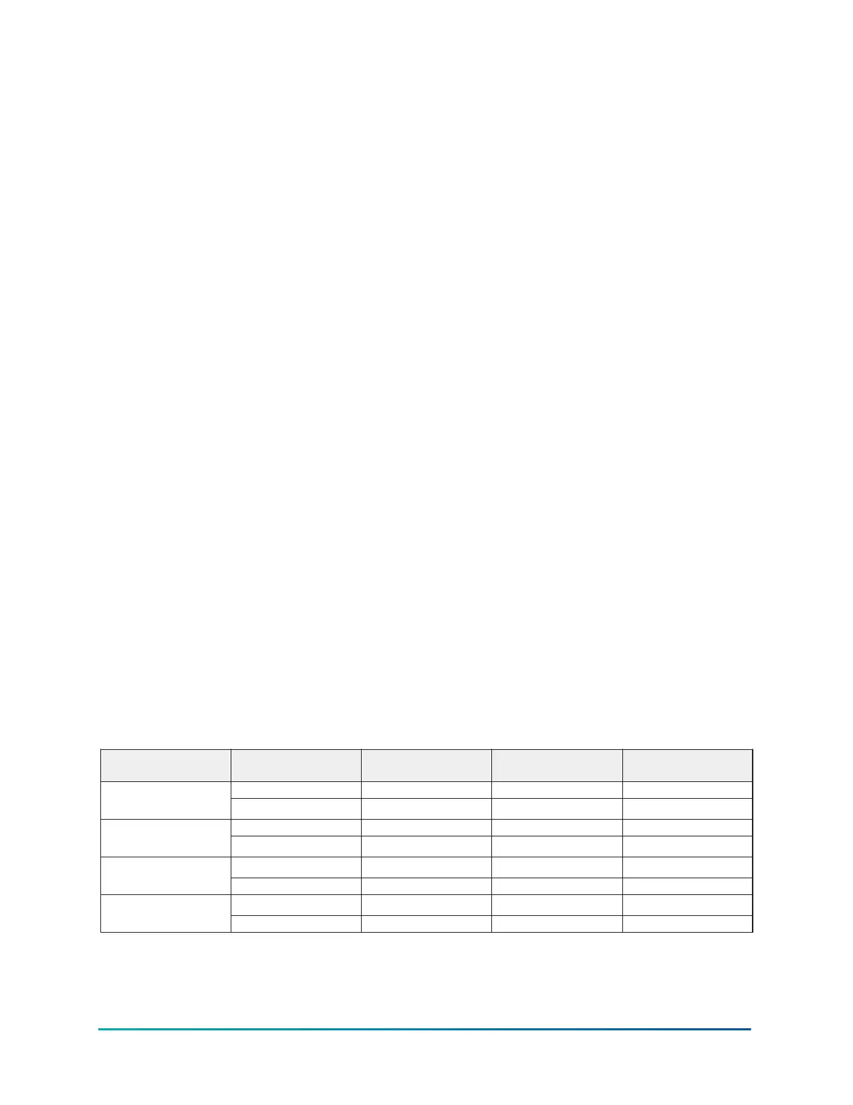
Table 4: Fail safe information
C450 output function Factory default setting Desired fail-safe state Output relay contact
wired
NRGZ value for relay
Yes ON N.C. OFFRefrigeration:
Compressor or LLSV
OFF N.O. ON
Yes ON N.C. OFFSingle or high-speed
evaporator fan
OFF N.O. ON
ON N.C. OFF
Low-speed evaporator
fan
Yes OFF N.O. ON
ON N.C. OFF
Defrost heater
Yes OFF N.O. ON
15System 450 Series C450CCU Condensing Unit Control System Technical Bulletin

 Loading...


