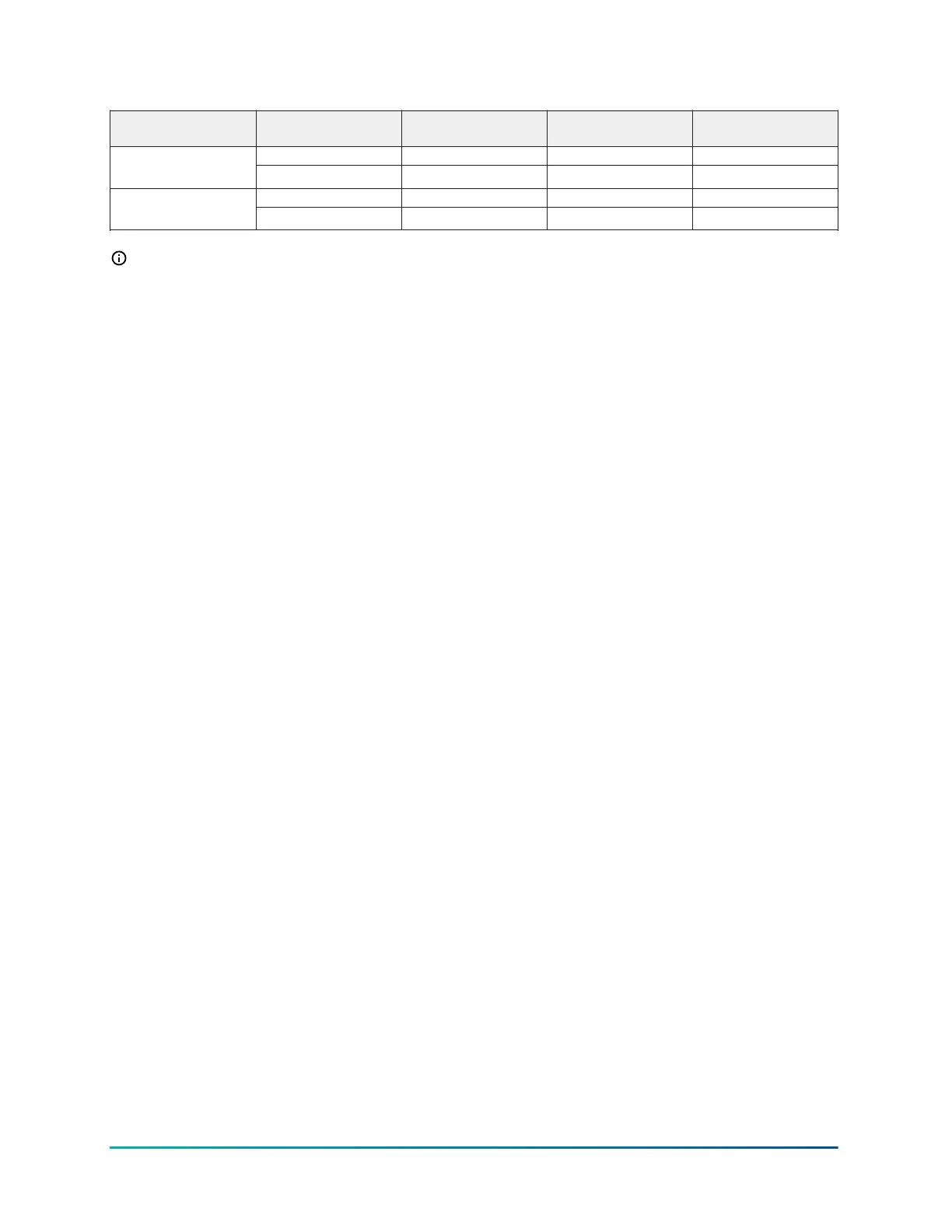
Table 4: Fail safe information
C450 output function Factory default setting Desired fail-safe state Output relay contact
wired
NRGZ value for relay
Yes ON N.C. OFFPump down or
Compressor
OFF N.O ON
Yes ON N.C. OFFAlarm
OFF N.O. ON
Note: For pump down systems, the refigeration control logic requires a N.C. LLSV. This ensures
the default failure mode is similiar to a compressor for a desired fail-safe state of ON.
Relay Staging Delay
The relays on the CCU Control Module and System 450 Expansion Modules have a built-in one
second time delay between relays. In the event that relays on both modules change state at the
same time, the delay, between the relay state changes, reduces the possibility of high in-rush
current to the refrigeration system. This results from two loads energizing at the same instant.
Using the example of a System 450 set-up with a C450CCU Control module and a C450SCN 2-relay
Expansion module that experiences a power failure. When the power restores, the first relay in
each module energizes at the same time and one second later the second relay in each module
energizes. This prevents the loads on all four relays from potentially energizing at the same time.
Expansion module fail safe feature
The System 450 Expansion Modules behave differently when used with a C450CCU control module
in comparison to their behavior when used with other C450 Control Modules. Normal behavior
when communication is lost from a Control Module is the Expansion Module leaves the relays in the
last commanded state until communication restores or power is lost to the Expansion Module.
When the Expansion Module is used with a C450CCU, if it does not receive a command from the
Control Module for a period of two minutes, the relay or relays on the Expansion Module de-
energize and fail safe to their normal state. The LC/LNC contacts close and the LC/LNO contacts
open. If the Expansion Module has two relays, there is a one second time delay between de-
energizing the relays.
Sensor failure mode
In the event of a refrigerated space temperature sensor Sn-1 failure, or sensor wiring failure, use
the sensor failure mode of operation for the refrigeration output. When you set up the refrigeration
output in the condensing unit control module UI, select a sensor failure mode of operation in the
sensor failure mode (SNF) screen. Your selection determines how the refrigeration output responds
if sensor 1 or the sensor 1 wiring fails.
When Sn-1 or the associated sensor wiring fails, the refrigeration output goes into the selected
sensor failure mode and continues to operate in the sensor failure mode until you correct the
sensor or sensor wire failure.
Select either ON, OFF or CYC for a Sn-1 sensor failure mode. For Sn-1, ON, OFF and CYC sensor
failure modes are as follows:
• Refrigeration ON
• Refrigeration OFF
System 450 Series C450CCU Condensing Unit Control System Technical Bulletin16

 Loading...


