Table 5: C450CCU condensing unit control system
Callout Description
11 Low-speed evaporator fan control circuit; optional, OUTR3 (24 VAC to 240 VAC)
12 Defrost control circuit; optional, OUTR4 (24 VAC to 240 VAC)
13 Pump down or compressor control circuit; optional, OUTR5 (24 VAC to 240 VAC)
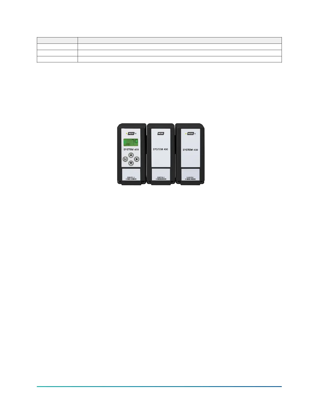
Assembling System 450 modules
When you select the System 450 components for your control system, you can assemble the
modules.
Figure 4: System 450 module assembly
Observe the following guidelines when you assemble System 450 modules:
• Always locate the control module on the left side of the module assembly.
• When you use the System 450 power module, plug it into the right side of the control module.
• Plug the expansion module on the right side of the System 450 power module or on the right
side of the control module when you use an external 24 V power supply instead of a System
450 power module. See Wiring for information about wiring an optional external 24 VAC supply
power to System 450 control systems that do not include a power module.
System 450 module mounting
Observe these guidelines when you position and mount System 450 modules:
• Make sure that the mounting surface can support the module assembly, DIN rail, mounting
hardware, and any user-supplied panel or enclosure.
• Mount the modules in a horizontal, upright orientation wherever possible. It is best practice to
mount the modules on a DIN rail.
• In direct-mount applications, mount the modules on flat and even surfaces.
• Mount the modules in a location free of corrosive vapors and observe the ambient operating
conditions listed in System 450 Series C450CCU Condensing Unit Control System technical
specifications.
• Allow sufficient space for connections, run wires, and to view the LCD.
System 450 Series C450CCU Condensing Unit Control System Technical Bulletin18

 Loading...


