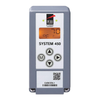
Setting up a condensing unit control system
When you assemble the modules, you can connect your System 450 control system to a power
module. You must connect the power module to either a 120 VAC or 240 VAC power source and you
must connect it to the right of the control module. When you apply power, you can then set up the
system in the control module UI.
You must set up the sensors and transducers in the System 450 UI before you can set up any of
the control system outputs. See Setting up the sensors and transducers for more information and
detailed procedures.
User settings and parameters
Table 9: System settings
Symbol Settings Default
setting
Description
Sn-1 °F, °C °F Space temperature sensor
• The setting defines the type of space temperature sensor.
Sn-2 --, °F, °C, or bin -- or None Defrost termination sensor
• This setting defines the type of defrost termination sensor.
Sn-3 -- or None
P100 psi
P110 or psi
P200 or psi
P8 or bar
P15 or bar
-- or None Suction pressure transducer
For more information on pressure transducers and corresponding
pressure ranges, see Table 3
OFFS1 +/- 5°F or
+/- 3.0°C
0 Offset Sn-1:
• Error offset for Sensor Sn-1
OFFS2 +/- 5°F or
+/- 3.0°C
0 Offset Sn-2:
• Error offset for Sensor Sn-2
OFFS3 +/- 10 psi
+/- 0.70 bar
0 Offset Sn-3:
• Error offset for Sensor Sn-3
dTYP PASS
ACt
PASS Defrost type:
• Set the defrost type to either active, ACt, or passive, PASS.
• Active defrost uses a relay output to energize an electric heater.
ETYP EF-1, EF-2 EF-1 Evaporator fan type:
• Set the evaporator fan type to single speed, EF-1, or two speed,
EF-2.
• If you set the fan type to EF-1, you require a relay output to
energize the single speed fan.
• If you set the fan type to EF-2, you require two relay outputs to
control the two-speed fan. The relay assigned to EF1R activates the
Hi-speed fan and EF2R activates the Lo-speed fan. Both fan outputs
are active for Lo-speed operation.
CLK Clock format 12 HR mode Clock format
• Set the parameter to 12 HR and apply to all time values.
SETT Clock: real-time Real-time clock setting
• The clock is battery backed and remains operational when the
control is powered down for several days.
bKLL Backlight: low-level Low The backlight low-level defines the backlight level when you do not use
the UI.
bKLH Backlight: high-level High The backlight high-level defines the backlight level when you access the
UI and make adjustments to the user settings.
System 450 Series C450CCU Condensing Unit Control System Technical Bulletin24

 Loading...


