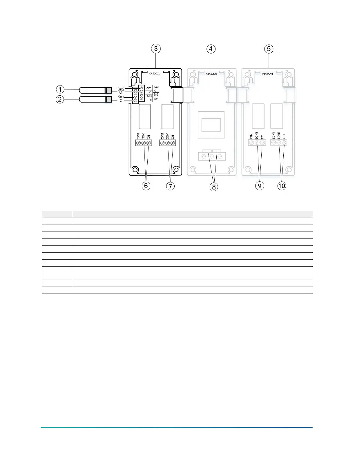
Figure 11: Active electric heat defrost control system
Table 18: Active electric heat defrost control system
Callout Description
1 A99 temperature sensor; Sn-2 defrost temperature sensor
2 A99 temperature sensor; Sn-1 space termination sensor
3 C450CCU condensing unit control module
4 C450YNN power module
5 C450SCN relay expansion module with two relay outputs
6 OUTR1, 24 VAC to 240 VAC: Controls refrigeration, either compressor or solenoid valve.
7 OUTR2, 24 VAC to 240 VAC: High-speed evaporator fan control circuit.
8
120 VAC or 240 VAC supply power terminals: Provide 120 VAC or 240 VAC supply power to optional C450YNN
power module.
9 Optional: OUTR3, 24 VAC to 240 VAC: Low-speed evaporator fan control circuit.
10 OUTR4 Defrost output
37System 450 Series C450CCU Condensing Unit Control System Technical Bulletin

 Loading...


