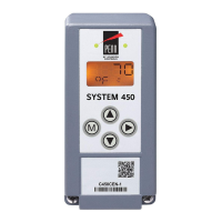
system outputs, including the expansion module outputs. See Ordering information for more
information.
Main screens
The main screens are default screens that autoscroll on the LCD during normal control system
operation. The main screens display the sensor status for each hard-wired and functional Sn-1 and
Sn-3 sensor, as well as the time of day. From the main screens, press the Next icon repeatedly to
manually scroll through the sensor status and output status screens. From the main screens, press
and hold the Up and Down icons simultaneously to go to the System Setup screens. See Accessing
and navigating the UI and Sensor and output status screens for more information.
OFFS
x
In the temperature and pressure offset selection (OFFS
x
) screen in the sensor setup screens,
select the value that you want the measured and displayed temperature and pressure values to
differ from the actual sensed temperature and pressure values. You can select an offset for each
temperature and pressure sensor in your System 450 control system. The x value is the ID number
for the temperature or pressure sensor you are setting up (Sn-1, Sn-2 or Sn-3). See Setting up the
sensors and transducers for more information.
Sensor type
Each System 450 compatible sensor and pressure transducer model associates with a specific
sensor type. Each sensor type provides the setup parameters that define the temperature,
pressure, unit of measurement, usable range, resolution, and minimum proportional band for the
associated sensor and the outputs that reference the sensor. You must select Sn-1, Sn-2 or Sn-3
sensor type, °C or °F and psi or bar, for each sensor that you connect to your control system when
you set up the sensors for your control system. See Setting up the sensors and transducers for
more information.
SENS
x
SENS appears in several screens in the System 450 UI and is associated with either the initial sensor
setup screens, or the sensor selection and sensor edit screens in the output setup screens. In the
sensor setup start (SENS) screen, press Next to go to the sensor setup screens and set up the hard
wire sensors for your control system. There is no output ID number (x) in the sensor setup start
screen. See Setting up the sensors and transducers for more information.
Sn-1
Input sensor 1, Sn-1, as identified in the System 450 condensing unit control module UI. The
refrigeration output references the temperature sensor that is hard-wired to the Sn-1 terminal and
a Common (C) terminal on the low-voltage terminal block on the system’s control module. See
Setting up the sensors and transducers for more information.
Sn-2
Input sensor 2, Sn-2, as identified in the UI. Defrost termination for active defrost type references
the temperature or binary sensor that is hard wired to the Sn-2 terminal and a Common (C)
terminal on the low-voltage terminal block on the system’s control module. See Setting up the
sensors and transducers for more information.
Sn-3
Input sensor 3, Sn-3, as identified in the UI. Pump down control references the pressure transducer
that is hard wired to the Sn-3 terminal and a Common (C) terminal on the low-voltage terminal
block on the system’s control module. For more information, see Setting up the sensors and
transducers.
System 450 Series C450CCU Condensing Unit Control System Technical Bulletin44

 Loading...


