12
FORM 145.18-IOM1
ISSUE DATE: 8/30/2018
SECTION 1 - INSTALLATION
1. Place the cabinet in a horizontal position on the
oor adjacent to its installation location (when ris-
ers are attached to cabinet).
The units are designed to accommodate a maxi-
mum supply and return riser stub-out movement
of 1-1/2 inches due to expansion and contraction
(total movement of 3 inches). If the total calcu-
lated riser expansion or contraction exceeds 1-1/2
inches, the field must provide expansion compen-
sation.
2. Install eld or factory-provided riser extensions,
if required, to the unit-mounted risers prior to
moving the cabinet into nal position.
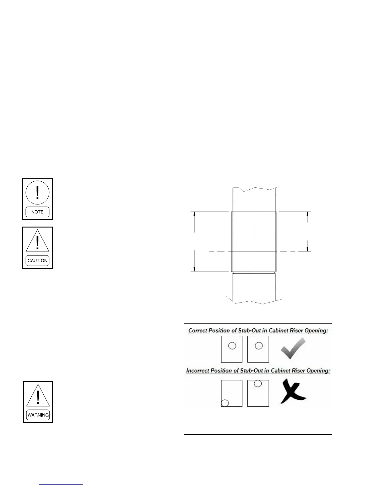
3. Raise the cabinet upright. Lower the risers through
the oor cutout, aligning the risers into the swaged
section of the unit on the oor below.
Take extra care not to scrape or dent ris-
ers during positioning. The riser tailpiece
should insert approximately 2 inches into
the 3-inch long swaged section of the unit
below.
DO NOT allow the riser tailpiece to bottom
out into the swaged section. This ensures
the correct riser positioning and com-
pensates for variations in oor-to-oor
dimensions.
4. Center the risers in the pipe chase, and level the
cabinet using shims as necessary.
5. Plumb risers in two planes to assure proper unit
operation and condensate drainage.
6. Anchor the cabinets into place using rubber iso-
lated sheet metal angles. Approved and tested
sheet metal angles are available from factory.
It is strongly recommended to install vibration
isolation pads to reduce noise transmission into
the floor. Failure to use isolation kits could result
in loud unit operation.
Do not drill or drive screws into the cabi-
net in the area of the internal drain pan.
7. Center the risers’ horizontal stub-outs (complete
with factory-installed shut-off valves) in the cabi-
net slot openings. Ensure that the stub-outs are
perpendicular to the side/back panel.
8. Verify all risers are vertical and that they penetrate
the swaged joint at least 1 inch.
Factory provided risers come with a 3-inch deep
swage. Do not allow risers to completely bottom
out at 3 inches in the swage. The 3-inch swage
depth is oversized to allow for adjustments if nec-
essary to keep riser stub-outs and valves centered
in the cabinet opening.
9. Center the riser stub-out in cabinet opening to
allow for expansion and contraction. Riser stub-
outs must not contact on any sheet metal opening.
Otherwise damage can occur to stub-outs, result-
ing in water leaks and property damage.
Top Vertical
Riser
Bottom
Vertical Riser
2-inch Ideal
Insertion Depth
3-inch Cup
Height
LD23535
FIGURE 1 - IDEAL RISER INSERTION DEPTH
LD19017
FIGURE 2 - CORRECT/INCORRECT STUB-OUT
POSITIONS IN CABINET RISER OPENING