31
SECTION 1 - INSTALLATION
FORM 145.18-IOM1
ISSUE DATE: 8/30/2018
1
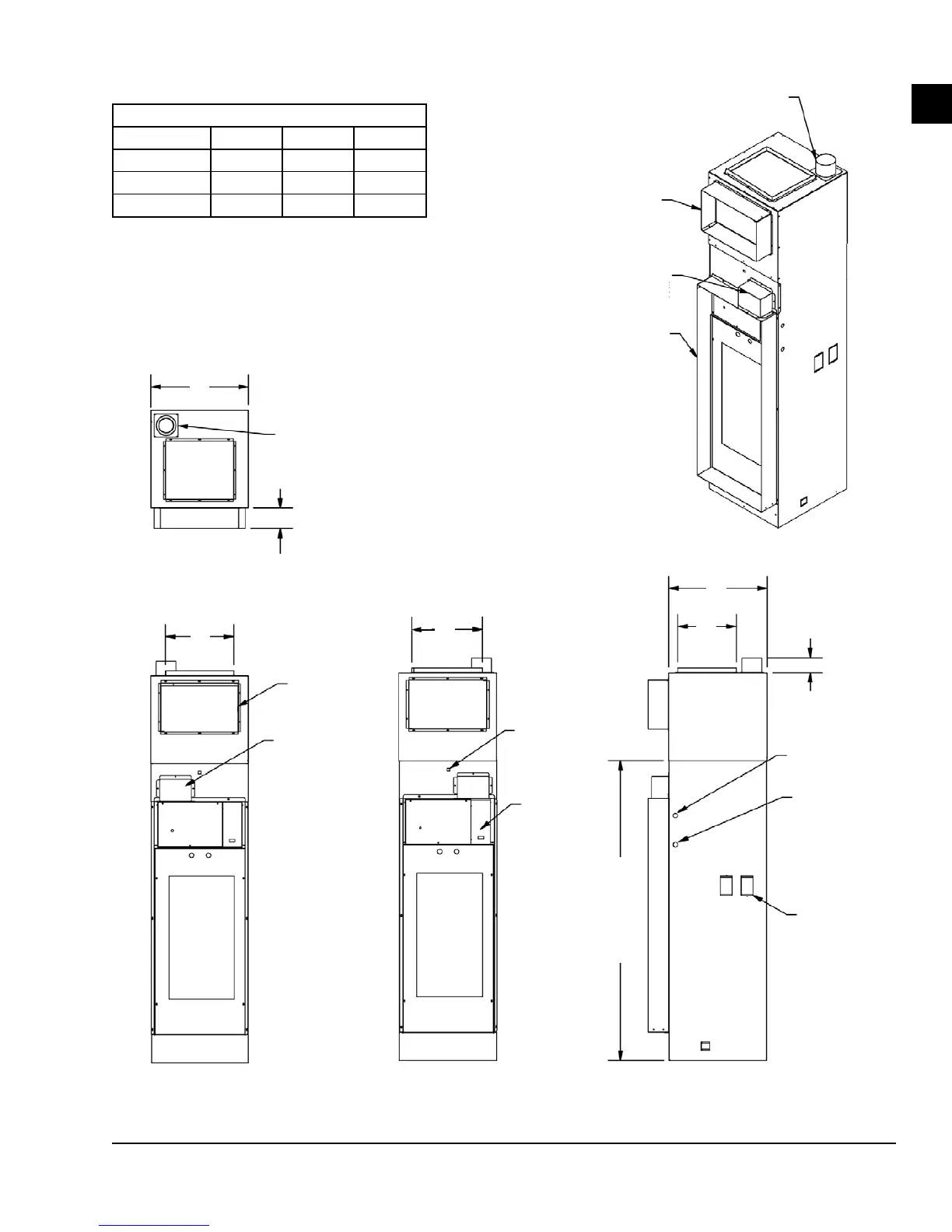
4-inch Ø Fresh Air
Take-Off Intake
Optional Front Supply
(4.25-inch Flange)
Fresh Air Discharge
Collector Box
4.25-inch Return Air
Flange
4-inch Ø Left Hand Fresh Air
Take-Off Intake
A
A
B
C
C
4.25 inches
Optional Front
Supply
(4.25-in. Flange)
Optional 24V
Molex Connection
for Surface Mount/
Remote Mounted
Thermostat
Unit Switch
Plate
Fresh Air
Discharge
Collector Box
3 inches
61-7/8 inches
Ø 7/8-inch
Power
Entrance
Ø 7/8-inch
Control
Entrance
(Knock-Out,
Both Sides)
Riser
Opening
Knock-Outs
(All Three
Sides)
CABINET DIMENSIONS (INCHES)
MODEL A B C
09–12 17 8 12
15–24 20 12 14
30–36 24 16 18
1. Optional fresh air option comes with 4.25-inch RA ange.
2. Optional front supply opening comes with 4.25-inch duct ange.
3. All other openings come with standard 1-inch duct ange.
4. Left and right hand versions shown.
LD27634
FIGURE 22 - FRESH AIR OPENING WITH MOTORIZED DAMPER – LEFT AND RIGHT HAND UNIT SHOWN