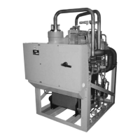
Variable speed drive
A variable speed drive will be factory packaged with the chiller. It is designed to vary the
compressor motor speed by controlling the frequency and voltage of the electrical power to the
motor. The control logic automatically adjusts motor speed as required to suit lift and capacity
requirements.
Power panel
The power panel includes the uninterrupted power supply and power storage battery. These feed
essential loads while the chiller shuts down upon loss of main chiller power.
Optional service isolation valves
If the chiller is equipped with optional service isolation valves on the discharge and liquid line,
these valves must remain open during operation. These valves are used for isolating the refrigerant
charge in either the evaporator or condenser to allow service access to the system. A refrigerant
pump-out unit is required to isolate the refrigerant.
CAUTION
Isolation of the refrigerant in this system must be performed by a qualified service technician.
Optional hot gas bypass
Hot gas bypass is optional and is used to provide greater turndown than otherwise available for
load and head conditions. The OptiView
™
control center will automatically modulate the hot gas
valve open and closed as required. Adjustment of the hot gas control valve must only be performed
by a qualified service technician.
OptiView
™
Control Center
The YORK OptiView
™
Control Center LCD graphic display and keypad is the interface for starting,
stopping, configuring, monitoring, and commanding the chiller controls. The control center
is a microprocessor based system for centrifugal chillers. It controls the leaving chilled liquid
temperature (LCHLT) and maintains safe operation. It is factory-mounted, wired, and tested.
The graphic display allows the presentation of operating parameters in logical groups on screens
and can trend data to present a graphical representation of present or historical operation of the
chiller. The locations of various chiller parameters are clearly and intuitively marked. Instructions
for specific operations are provided on many of the screens. The screens and navigation are shown
in the OptiView Control Center functions and navigation section.
Eight buttons are available on the right side of the panel, and are primarily used for navigation
between the system screens. At the base of the display are five additional buttons. The button
functions are redefined based on the currently displayed screen. The area to the right of the keypad
is used for data entry with a standard numeric keypad provided for entry of system setpoints and
limits.
YMC
2
Mod B with OptiView Control Center
14

 Loading...


