YDFLP Fiber Laser Installation
Guide and User Manual
FileNumber:EFLP001‐B‐E ShenzhenJPTOpto‐electronicsCo.Ltd.
Version:BDate:2016.4
14
3. Control and Monitoring Interfaces
3.1 Control Interface
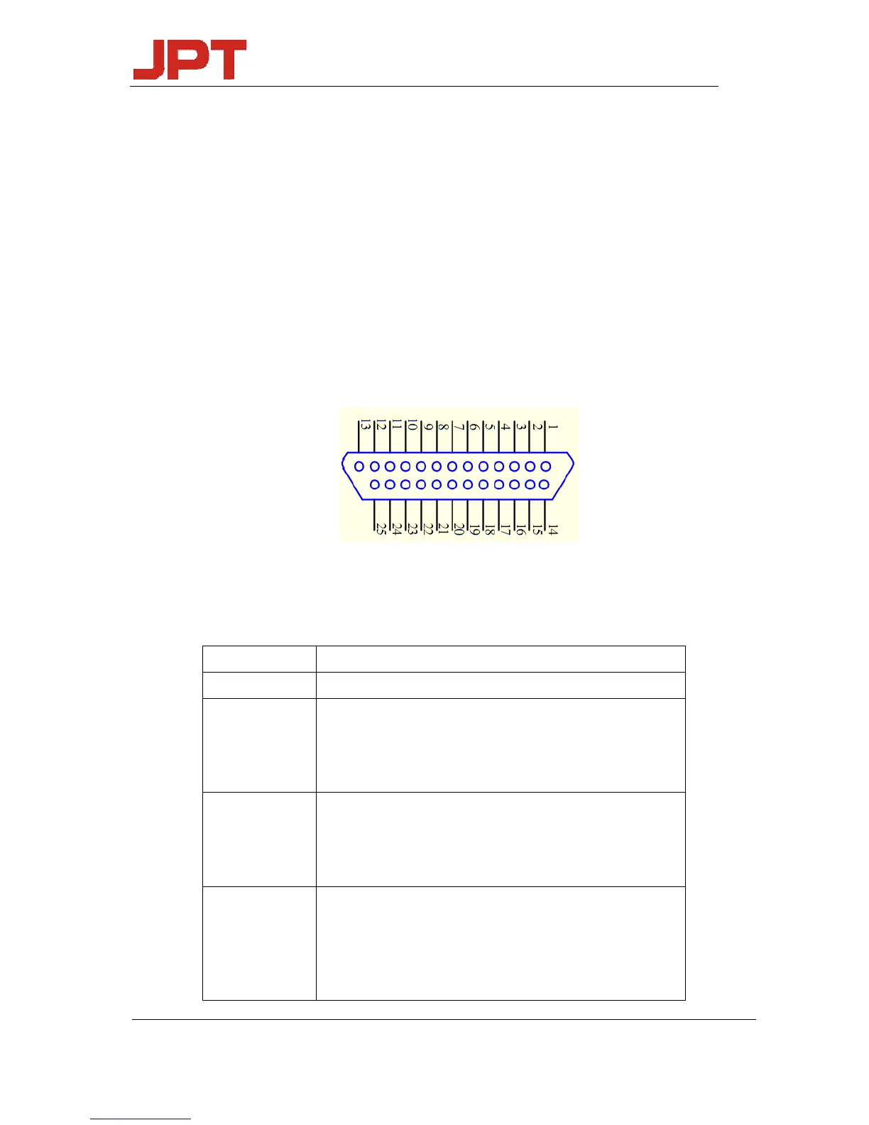
DB25 behind the power module is the interface used to connect the control system (such as
marking machines) to the laser system. Please make sure that the interface is connected firmly
before the operation.
The PIN is defined as shown in Figure 10 and Table 6.
Figure 10 DB25 interface
Table 6 DB25 interface definition
DB25PIN# Description
1‐8 IP0‐IP7PowerControl
10‐15 GND
Description: PIN10‐15 have connected inside fiber laser,only
needtoconnectcontrolcardGNDwithanotherPin
16,21
Warningsignal
Description:16lowlevel,21highlevel:Normal
16lowlevel,21lowlevel:temperaturealarm
19
Laserstartingsignals(PA)showsthathighlevelisjustasopen
andlowlevelisjustasoff.
IfPIN19atthehighlevelbeforeaddthe24VDCmainpower
supply,thefiberlasercan’trecognize(PA)ison‐state