*Note: The RF Transmission Indicator will not be on when the
display switch is activated. Also it wll not be illuminated when
there is not a module installed in the transmitter.
**Note: Steering Tension is adjustable via the Phillips head
screw recessed next to the idle up switch. Screwing clockwise
increases the steering tension.
Display Switch
The display switch allows the input of data without transmit-
ting a signal. This is useful for making adjustments while
not affecting others that may be on the same frequency. With
the power switch off, turning on the display switch will acti-
vate the display and all programming functions can be
accessed. This also uses about 2/3 less power; if you plan
on working with the programming for a while, using the dis-
play switch will save batteries.
Note: The antenna included with the R-1 is the screw-in
type (part #JRPA160). When in use, be sure the
antenna is screwed in firmly, and the antenna is
extended fully.
4
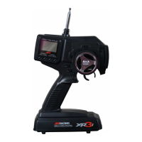
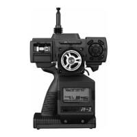
1 Antenna
2 RF Transmission Indicator*
3 Power Switch
4 Display Indicator
5 Charge Jack
6 D.S.C. Jack
7 Display Switch
8 Timer Button
9 Drive Mode Switch
10 Grip Trimmer A
11 Grip Trimmer B
12 Throttle Digital Trimmer
13 Steering Digital Trimmer
14 Auxiliary 3 Channel (Ch3)
15 Idle Up Switch
16 Steering Tension Adjustment**
17 Dot Matrix Graphic Display
18 Steering Wheel (Ch1)
19 Throttle/Brake Lever (Ch2)
20 Key Pad
Control Identification
17
19
15
16
14
20
18
13
1
122
4
3
7
6
5
10
9
8
11
 Loading...