13
(5) Transducer Cable Wiring Procedure
1. Don't try to bundle the transducer cable with other cables. When this cable is
routed along with another cable, 50 cm minimum space must be provided between
the them.
2. The cable on the echo sounder transducer tends to pick up or generate noise, thus
it must not be bundled with the coaxial cable on the radio equipment.
3. It is recommended to route the transducer cable through iron pipe.
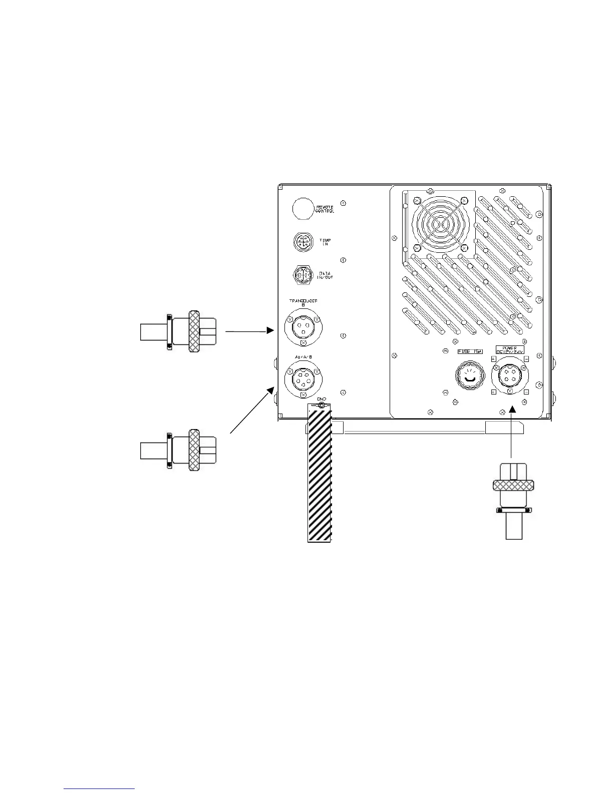
Power Supply and Transducer Connectors Connection Diagram
To the transducer
Low frequency side when the
single or dual frequency mode
is selected.
High frequency side when
the dual frequency mode is
selected.
Ground
0.5×30
Copperplate
Powerconnector
HS21P‑4
For DC specs., connect the 7ZCBS0827A (CFQ-8827) to the inboard power supply.
For AC specs., connect the 7ZCBS0827A (CFQ-8827) to the NBA-3263 rectifier.
Use DPYCY-2.0 (or higher in ratings) as an extension power cable.
 Loading...


