12
2.3 Connecting the Power Supply and Transducer Connectors
(1) Connecting the Power Cables
1. Use 7ZCNA0827A(CFQ-8827) for the power cable.
2. Connect the power cables as indicated below:
3. When the installation requires to extend the power cable, the cable used must be
DPYC-2.5 or above so that voltage on the connector when conducted may not go
10.2V or less.
4. At powering on, 8A current (10.2V) is conducted to the JFV-700HP for two sec-
onds. Current capacity of a circuit breaker, if any, must be suitable for the above
current.
5. If you connect the power cable to the power terminal used on the radio equipment,
noise can be generated on the equipment.
(2) Power Cable Connecting Procedure for AC specification
1. Connect NBA-3263 rectifier to the AC power supply (100/110/220V), then connect
the power cable to the rectifier.
(3) Power Cable Wiring Procedure
1. Don't try to bundle the radio equipment coaxial cable with the echo sounder power
cable. Such practice can generate noise on the radio equipment.
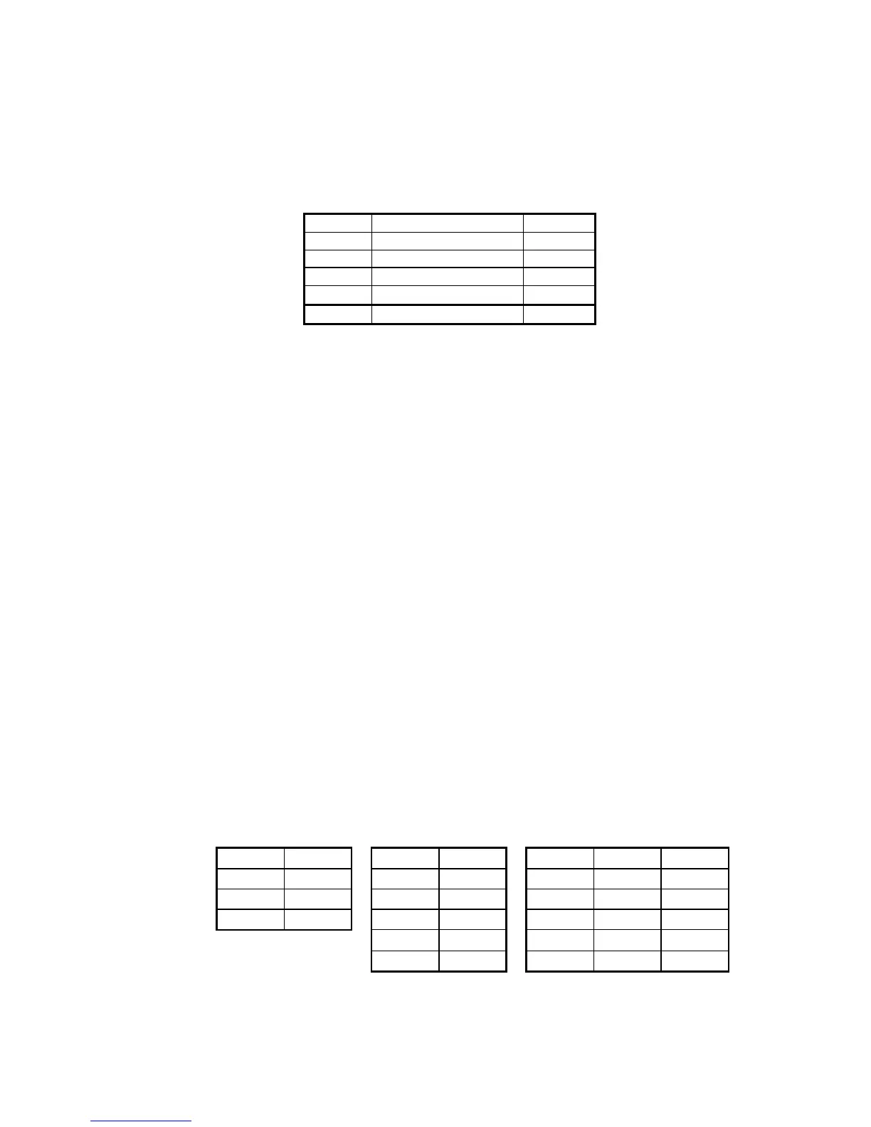
(4) Transducer Cable Connecting Procedure
1. Connectors are attached to the transducer. Connect the cables to the connectors
as indicated below, then solder them to the connectors.
Connector BConnector A/B or AConnector A/ B or A
transducer for a single, transducer for
dual or low frequency dual and high frequency transducer for dual frequency
Cable
Pin No.
Cable
Pin No.
Cable
Pin No.
Freq.
White
1
-
1
White
1 Low
Shield
2
White
2 Red 2 High
Black
3
Shield
3
Shield
3
Black
4 Green 4 High
-
5
Black
5 Low
Connector type HS21P−3 HS21P−5 HS21P−5
Cable Connector pin number Polarity
Red 1 +
White 2 +
Black 3 -
Green 4 -
Shield Connector case -
 Loading...


