36
4 Frequency Change
4.1 Changing to Single Frequency
Adjust the following components on the CML-560-1K/3K. For the entire view of the
CML-560-1K/3K , see Figure 4.1 in page 40.
1. When 200 kHz is selected, move the jumper pins JP721, 722, 725 and 726 to the
position indicated in Table 4.1 of page 41. When 75, 50, 38 or 28 kHz is selected,
move the jumper pins JP JP723, 724, 727 and 728 to the position indicated in the
same figure.
●
JP701 and JP702, JP03 and JP704
same time. Changing a single alone can damage the transmitter.
●
Whenever a setting is changed, implement the master reset being
followed by the transducer selection (see Section 4.3 in page 43 for
the selection).
Selecting a transducer not installed can damage the transmitter or
the transducer.
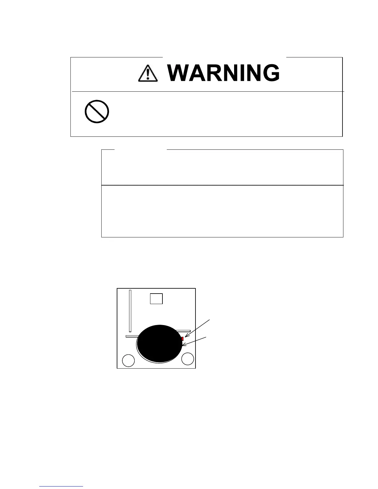
Do not start your operation as long as the CD857 LED is turned on.
Otherwise, electric shock can result from touching the high potential
block.
CPU
CD857:Indication for high voltage.
See the following 1, 2 and 3.
 Loading...


