6-22
6.5.3 SENSOR/DATA2 connector (MID/GPS)
Display Unit Rear
MID
Terminal
Number
Name Explanation
1 -
Unused
2 -
3 White Serial
transmission
(DATA IN 4)
RXD2-B
Input to the specification set by “DATA IN/OUT4.”
4 Green RXD2-A
5 Yellow Serial
transmission
(DATA OUT 4)
TXD2-A
Output to the specification set by “DATA IN/OUT4.”
6 Brown
TXD2-B
GPS Navigator
Terminal
Number
Name Explanation
1 Red
Power supply
output
DCOUT+
Supplies power to the DGPS/GPS sensor.
2 Black DCOUT-
3 White
Serial
transmission
RXD2-B
Receives data from the DGPS/GPS sensor.
4 Green RXD2-A
5 Yellow
Serial
transmission
TXD2-A
Sends configuration data to the DGPS/GPS sensor.
6 Brown
Not Use
1 5
6
2 4
3
Display Unit Rear: Connector Pin Number
CFQ5767
Data cable (for MID)
CFQ-5767: 3 m (option)
Warning of GPS sensor connection
In this display, the voltage supplied to the display is supplied to a receiver as it is.
When you use receivers except JLR-4341/JLR-4340, set the power supply of a display to
DC12V. Supply of 24V will damage a receiver.
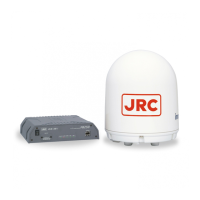
DGPS Sensor: JLR-4341
GPS Sensor: JLR-4340