CONNECTION
4
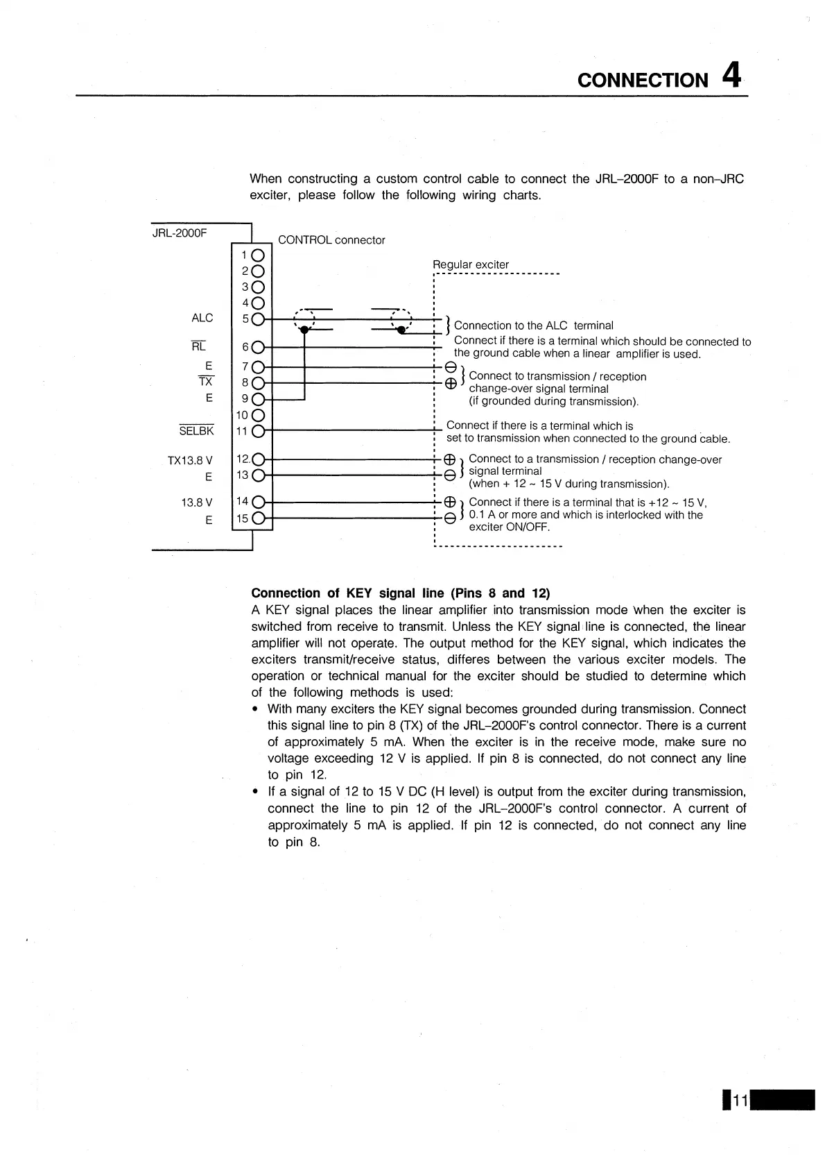
When constructing a custom control cable to connect the JRL-2000F to a non-JRC
exciter, please follow the following wiring charts.
ALC
SELBK
,A
CONTROL connector
Regular exciter
,______________________
Connection to the ALC terminal
Connect if there
IS
a
terminal which should be connected to
the ground cable when a linear amplifier is used.
Connect to transmission
I
reception
change-over signal terminal
(if grounded during transmission).
:
Connect if there is a terminal which is
:
set to transmission when connected to the ground cable.
to a transmission
1 reception change-over
13
slgnal terminal
1
(when
+
12
-
15
V
during transmission).
14
0
:
@
Connect if there is a terminal that is +12
-
15
V,
15
0
;
e
]
0.1 A or more and which is interlocked with the
exciter
ONIOFF.
I
Connection of
KEY
signal line (Pins
8
and
12)
A KEY signal places the linear amplifier into transmission mode when the exciter is
switched from receive to transmit. Unless the KEY signal line is connected, the linear
amplifier will not operate. The output method for the KEY signal, which indicates the
exciters
transmitlreceive status, differes between the various exciter models. The
operation or technical manual for the exciter should be studied to determine which
of the following methods is used:
With many exciters the KEY signal becomes grounded during transmission. Connect
this signal line to pin
8
(TX) of the JRL-2000F's control connector. There is a current
of approximately
5
mA. When the exciter is in the receive mode, make sure no
voltage exceeding 12
V
is applied. If pin
8
is connected, do not connect any line
to pin
12.
If a signal of 12 to 15
V
DC
(H
level) is output from the exciter during transmission,
connect the line to pin 12 of the
JRL-2000F's control connector. A current of
approximately
5
mA is applied. If pin 12 is connected, do not connect any line
to pin
8.