4
CONNECTION
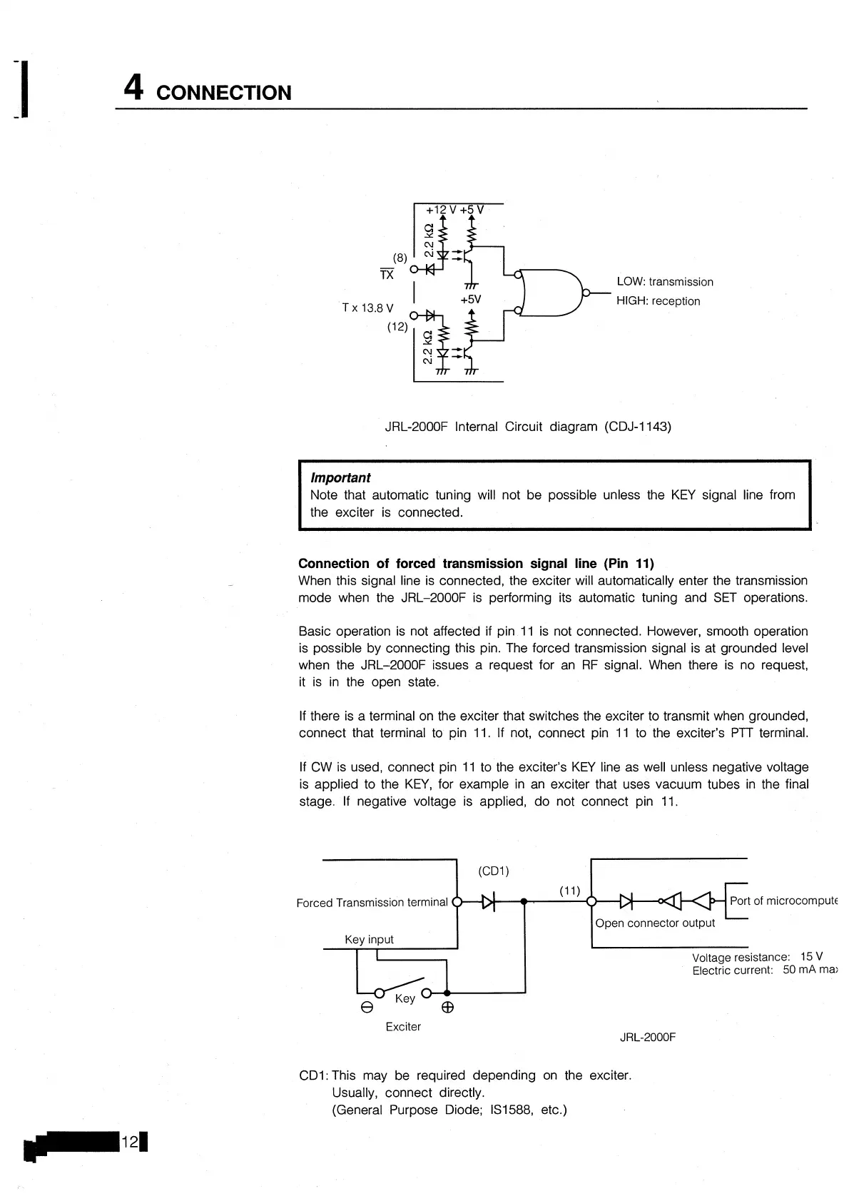
LOW: transmission
HIGH: reception
JRL-2000F Internal Circuit diagram (CDJ-1143)
Important
Note that automatic tuning will not be possible unless the KEY signal line from
the exciter is connected.
Connection of forced transmission signal line (Pin
11)
When this signal line is connected, the exciter will automatically enter the transmission
mode when the JRL-2000F is performing its automatic tuning and SET operations.
Basic operation is not affected if pin
11 is not connected. However, smooth operation
is possible by connecting this pin. The forced transmission signal is at grounded level
when the JRL-2000F issues a request for an RF signal. When there is no request,
it is in the open state.
If there is a terminal on the exciter that switches the exciter to transmit when grounded,
connect that terminal to pin
11. If not, connect pin 11 to the exciter's
PTT
terminal.
If
CW is used, connect pin 11 to the exciter's KEY line as well unless negative voltage
is applied to the KEY, for example in an exciter that uses vacuum tubes in the final
stage.
If
negative voltage is applied, do not connect pin 11.
Forced Transmission terminal
(1
1)
7
Port of microcompute
I
I
I
Open connector output
Key
input
-I-+
Exciter
I
\Joltage resistance:
15
V
Electric current: 50 nlA ma:
CDI: This may be required depending on the exciter.
Usually, connect directly.
(General Purpose Diode; 131588, etc.)