10
9
5
6
7
8
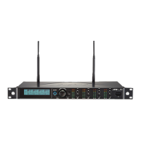
REMOSET:When the receiver setting is done, push to
transmit the setting data to the handheld or body-pack transmitter.
LCD display:See ''Receiver LCD display instructions.''
AF: indicates the current strength of audio frequency signals.
RF: indicates the current strength of radio frequency signals.
Key lock: push and hold for 2 seconds to lock all keys, and again to unlock.
Volume keys:push▲/▼keys to adjust the volume between 0 and -31dB.
Selection key:push this button
a. Push SETUP to enter the setting for the selected channel for parameter
settings.
b. Push REMOSET to transmit the setting data to the transmitter in this
selected channel.
AC Power Jack:connects 100-240VAC power.
AC power cascading:use AC double power cable (optional) for power
cascading.
XLR audio jack:balanced audio signal output
XLR audio jack:balanced audio signal output after mixing
Ø6.3 audio output jack:unbalanced audio signal output after mixing
Antenna A (B) input terminal:BNC antenna input jack that also provides
DC12V/100mA output.
RF signal A (B) output terminal: RF signal output jack; it is possible to
connect the RF A (or B) OUT of the rst unit to the antenna A (or B) IN of
the second unit with a BNC-BNC signal cable, and then the RF A (or B)
OUT of the second unit to the antenna A (or B) IN of the third unit, and so
on and so forth. The cascade may consist of up to 10 units to minimize the
number of antennas used.
10
11
12
13
14
14a
15
16
17
Note: Each cascading may bring1.2dB attenuation to RF signal.
 Loading...