– 3 –
II. SET-UP
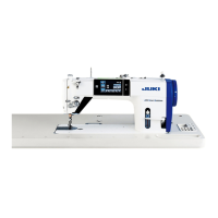
1. Installation
1) Carry the sewing machine with two persons as
shown in the gure above.
2) Do not put protruding articles such as the screw-
driver and the like at the location where the
sewing machine is placed.
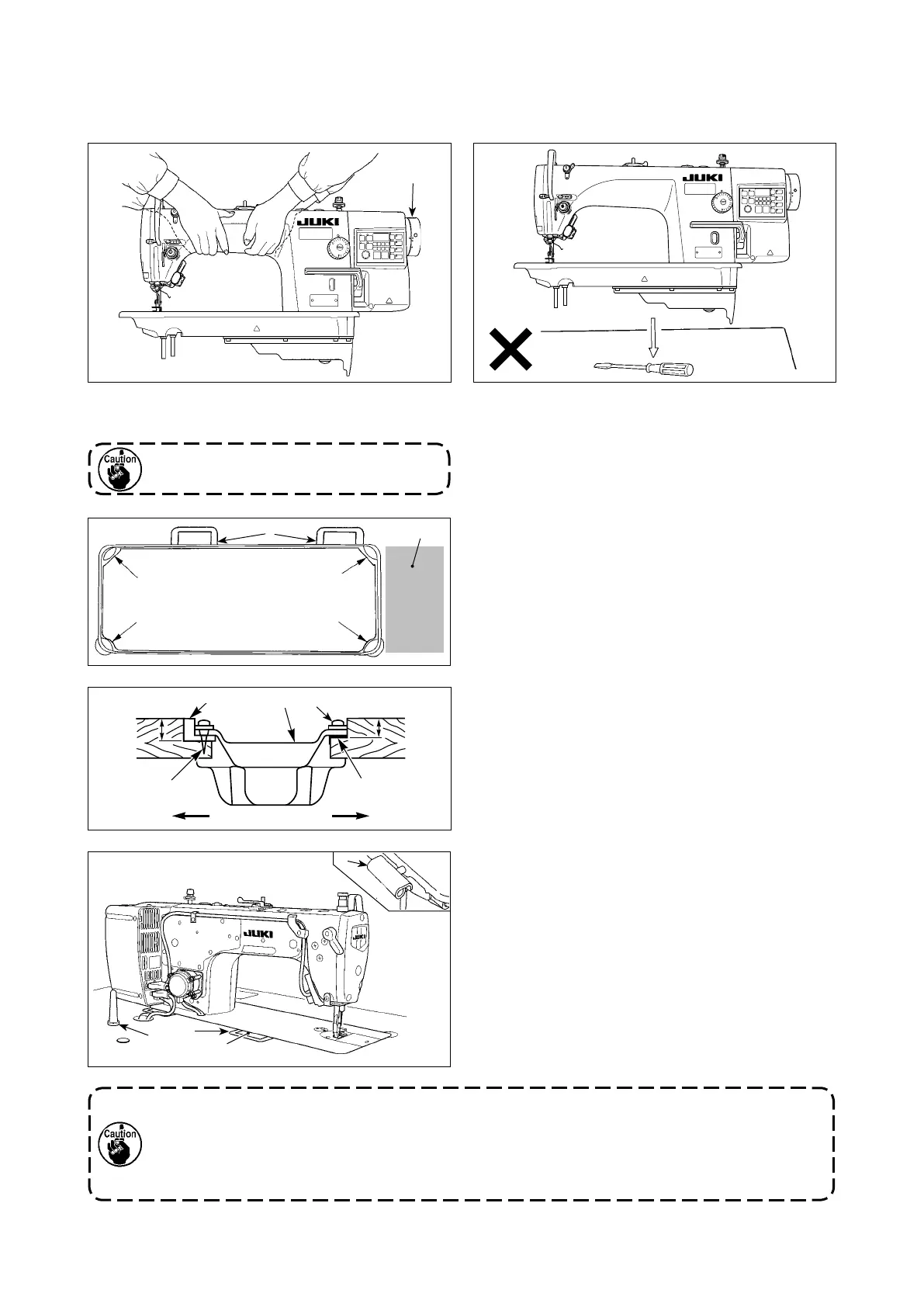
3) Adjust so that the underside cover is supported at
the four corners of the table. Mount rubber hinge
seat ❽ on the table and x it on the table with a
nail.
4) Two rubber seats ❶ for supporting the head por-
tion on the operator side A are xed on the ex-
tended portion of the table by hitting the nail ❷ ,
and the other two rubber cushion seats ❸ on the
hinge side B are xed by using a rubber-based
adhesive. Then, underside cover ❹ is placed.
5) Fit hinge ❼ into the opening in the machine bed,
and t the machine head to table rubber hinge ❽
before placing the machine head on cushions ❾
on the four corners.
6) Securely t machine head support stand ❻ in
the hole (60 x 141 x ø16, depth 30) (refer to H in
DRAWING OF TABLE p. 2) in the table.
Do not hold the handwheel D.
D
❶
❶
❸
❸
❽
C
19.5 mm23.5 mm
❶
❷
❹
❸
A B
❾
1. Be sure to install the machine head support rod ❻ supplied with the unit.
2. If a pair of scissors or the like is caught between the control box and the table, the control box
cover can break. To prevent such an accident, do not place anything on C section.
3. Be aware that the control box breakage and/or oil leakage can occur if operating the sewing
machine with the machine head support rod ❻ removed.
❼
❽
❼
❻
 Loading...