−11 −
Standard Adjustment
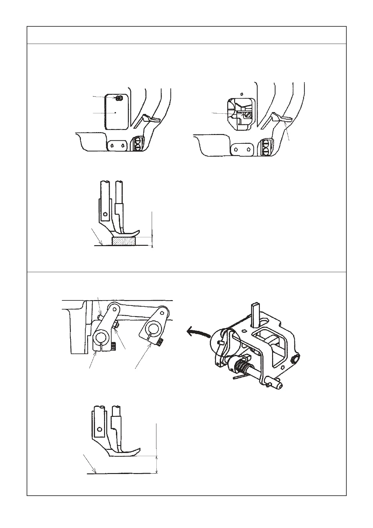
8) Presser lifter lever
9) Knee lifter
Top surface of
throat plate
Fig. 19
Condition
• State that the presser lifter
lever is lifted.
9 ± 0.3 mm
Fig. 18
Presser lifter
lever
①
②
③
Fig. 17
Top surface of
throat plate
Fig. 21
Fig. 20
* When the automatic presser foot lifter is attached,
refer to the item “(2) Automatic presser foot lifter”
of the Engineer’s Manual for LU-1500 series on
page 41.
Condition
• Lifting amount when the stopper screw
of knee-lifter lever A comes in contact
with the machine bed.
Knee-lifter
lever A
Knee-lifter
lever B
①
②
16 ± 0.5 mm
 Loading...