MV / MW
23
11. Electrical connections
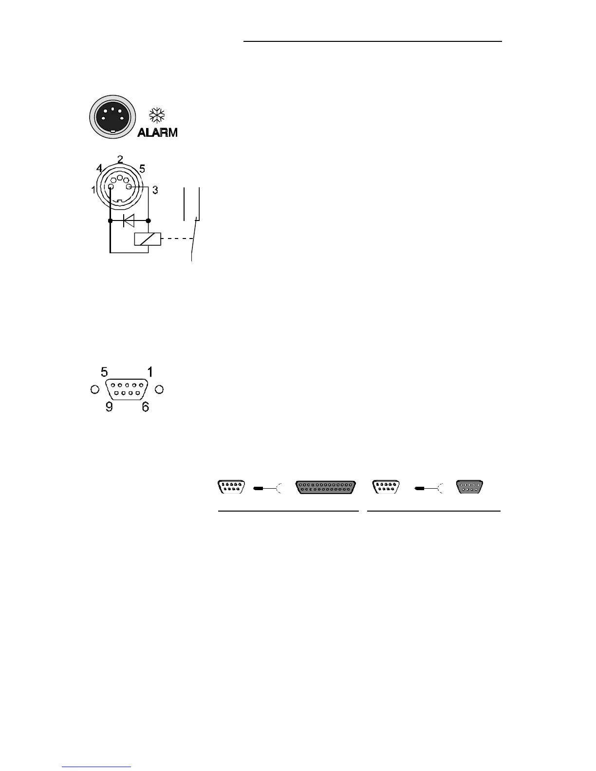
/ ALARM connector
The " ALARM" connector may be used as output for
alarm messages.
Circuit: Operation = relay powered
Alarm = relay not powered
Pin assignment:
Pin 1: +24 V (max. current 25 mA)
Pin 2: 0 V
Pin 3: Alarm relay
Pin 4: Reserved - do not use!
Pin 5: Cooling pulse
RS232C serial interface
This port can be used to connect a computer with an
RS232C cable for remote control of the circulator.
RS232C
Pin assignments:
Pin 2 RxD Receive Data
Pin 3 TxD Transmit Data
Pin 5 0 VD Signal GND
Pin 6 DTR Data terminal ready
Pin 7 RTS Request to send
Pin 8 CTS Clear to send
Interface correspondence:
Circulator Computer Circulator Computer
9-pole 25-pole 9-pole 9-pole
Pin 2 RxD ⇔ Pin 2 TxD Pin 2 RxD ⇔ Pin 3 TxD
Pin 3 TxD ⇔ Pin 3 RxD Pin 3 TxD ⇔ Pin 2 RxD
Pin 5 GND ⇔ Pin 7 GND Pin 5 GND⇔ Pin 5 GND
Pin 6 DTR ⇔ Pin 6 DSR Pin 6 DTR ⇔ Pin 6 DSR
Pin 7 RTS ⇔ Pin 5 CTS Pin 7 RTS ⇔ Pin 8 CTS
Pin 8 CTS ⇔ Pin 4 RTS Pin 8 CTS ⇔ Pin 7 RTS
Use shielded cables only.