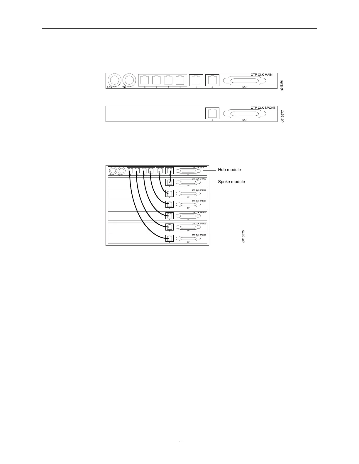
Figure 24: Clock Main Module
Figure 25: Clock Spoke Module
The clock main module accepts an external clock reference and distributes it to the spoke
module using a twisted pair cable. Each nonvoice card receives the clock on the first
RJ-45 and sends it to the front module.
Figure 26: Hub-and-Spoke Setup
Hub module
Spoke module
g015375
The main clock module has two BNC inputs (BITS and TTL), six RJ-45 ports, and one
DB-25 port. Each RJ-45 port can be connected to one spoke module. The spoke module
has one ingress RJ-45 port and one DB-25 interface. (See Figure 24 on page 26,
Figure 25 on page 26, and Figure 26 on page 26.)
Copyright © 2017, Juniper Networks, Inc.26
CTP2000 Hardware Documentation

 Loading...


