Figure 30 on page 61), the available RJ-45 console pinout will be the same as the console
connection on the RTM of PP332/PP310 processor.
Alternatively, if the DB-9 adapter from the bag labelled “p/n 720-056657” (see
Figure 31 on page 62) is used instead of “p/n 450-071855”, the available RJ-45 console
pinout will be similar to the CTP150 console port (and other Juniper routers). To connect
the PP833 processor with the DB-9 male serial port of a PC, additionally connect a
straight RJ-45 cable with the DB-9 adapter from the bag labelled “p/n 720-056657”.
The other end of the RJ-45 cable connects to the DB-9 adapter from the bag labelled
“p/n 720-014126” (see Figure 32 on page 62). Then, you can connect the PC’s DB-9 male
connector with the DB-9 adapter “p/n 720-014126”.
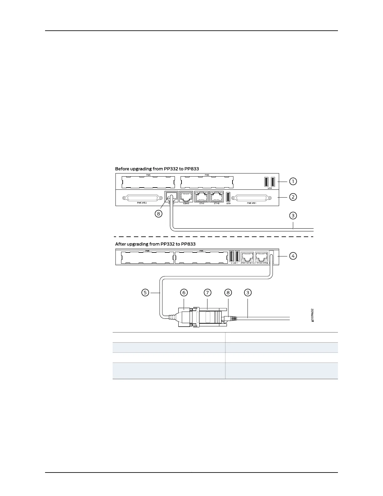
Figure 30: Upgrading from PP310/PP332 Processor to PP833 Processor
5—1— Cable 720-071594PP332 front panel
6—2— DB-9 male end of 720-071594PP332 RTM panel
7—3— Adapter 450-071855User’s existing console cable
8—4— RJ-45 male end of user’s existing console
cable
PP833 front panel
61Copyright © 2017, Juniper Networks, Inc.
Chapter 6: Cable and Pinout Specifications

 Loading...


