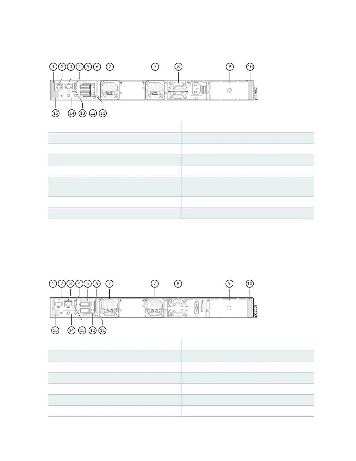
Figure 12: Components on the Rear Panel of an EX4400-24T Switch with an AC Power Supply
1—
Serial number ID label
9—
Empty slot for power supply
2—
Console port (labeled CON)
10—
Power supply rang label
3—
Management port (labeled MGMT)
11—
Electrostac discharge (ESD) point
4—
USB-A port
12—
QSFP28 port LEDs
5—
QSFP28 ports
13—
Reset buon
6—
Common Language Equipment Idener
(CLEI) code label
14—
Protecve earthing terminal
7—
Fan module
15—
Claim code label
8—
550-W AC power supply
Figure 13 on page 23 shows the components on the rear panel of an EX4400-24T switch with a DC
power supply.
Figure 13: Components on the Rear Panel of an EX4400-24T Switch with a DC Power Supply
1—
Serial number ID label
9—
Empty slot for power supply
2—
Console port (labeled CON)
10—
Power supply rang label
3—
Management port (labeled MGMT)
11—
ESD point
4—
USB-A port
12—
QSFP28 port LEDs
5—
QSFP28 ports
13—
Reset buon
6—
CLEI code label
14—
Protecve earthing terminal
7—
Fan module
15—
Claim code label
23