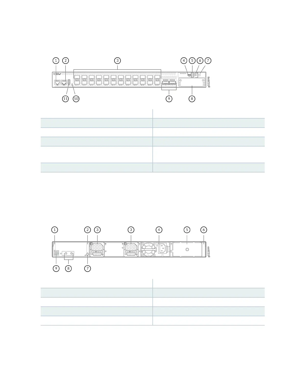
Figure 16: Components on the Front Panel of an EX4400-24X Switch
1—
Console port (labeled CON)
7—
Factory reset/mode buon
2—
Management port (labeled MGMT)
8—
Extension module slot
3—
24 SFP/SFP+ ports
9—
QSFP28 ports
4—
USB-C console port
10—
Reset buon
5—
Chassis status LEDs (labeled SYS, ALM, MST,
and CLD)
11—
USB-A port
6—
Port mode LEDs (labeled SPD, DX, and EN)
Figure 17 on page 29 shows the components on the rear panel of an EX4400-24X switch with an AC
power supply.
Figure 17: Components on the Rear Panel of an EX4400-24X Switch with an AC Power Supply
1—
Serial number ID label
6—
Power supply rang label
2—
CLEI code label
7—
ESD point
3—
Fan module
8—
Protecve earthing terminal
4—
550-W AC power supply
9—
Claim code label
5—
Empty slot for power supply
Figure 18 on page 30 shows the components on the rear panel of an EX4400-24X switch with a DC
power supply.
29