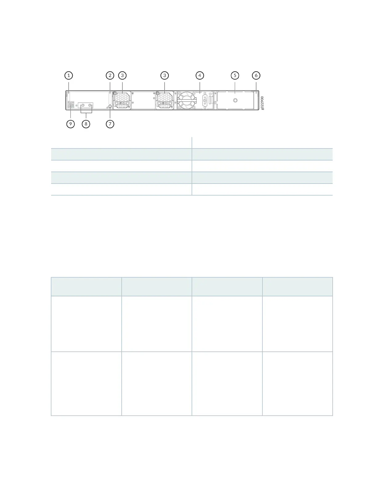
Figure 18: Components on the Rear Panel of an EX4400-24X Switch with a DC Power Supply
1—
Serial number ID label
6—
Power supply rang label
2—
CLEI code label
7—
ESD point
3—
Fan module
8—
Protecve earthing terminal
4—
550-W DC power supply
9—
Claim code label
5—
Empty slot for power supply
Table 14 on page 30 lists the components shipped with EX4400-24X switch models.
Table 15 on page 31 describes the physical specicaons, ports, and throughput of EX4400-24X
switches.
Table 16 on page 33 describes the power supply and cooling system specicaons of EX4400-24X
switch models
Table 14: EX4400-24X Switch Models, Shipped Components, and First Junos Release
Model Number Fan Modules Power Supply First Junos OS Release
EX4400
-24X
Two fan modules with
front-to-back airow
(indicated by the AIR
OUT label and the
Juniper Gold handle)
A 550-W AC power
supply with front-to-back
airow (indicated by the
AIR OUT label and the
Juniper Gold handle)
21.1R1
EX4400-24X-AFI Two fan modules with
back-to-front airow
(indicated by the AIR IN
label and the Juniper
Azure Blue handle)
A 550-W AC power
supply with back-to-front
airow (indicated by the
AIR IN label and the
Juniper Azure Blue
handle)
23.1R1
30