CAUTION: You must ensure that power connections maintain the proper polarity.
The power source cables might be labeled (+) and (–) to indicate their polarity. There
is no standard color coding for DC power cables.
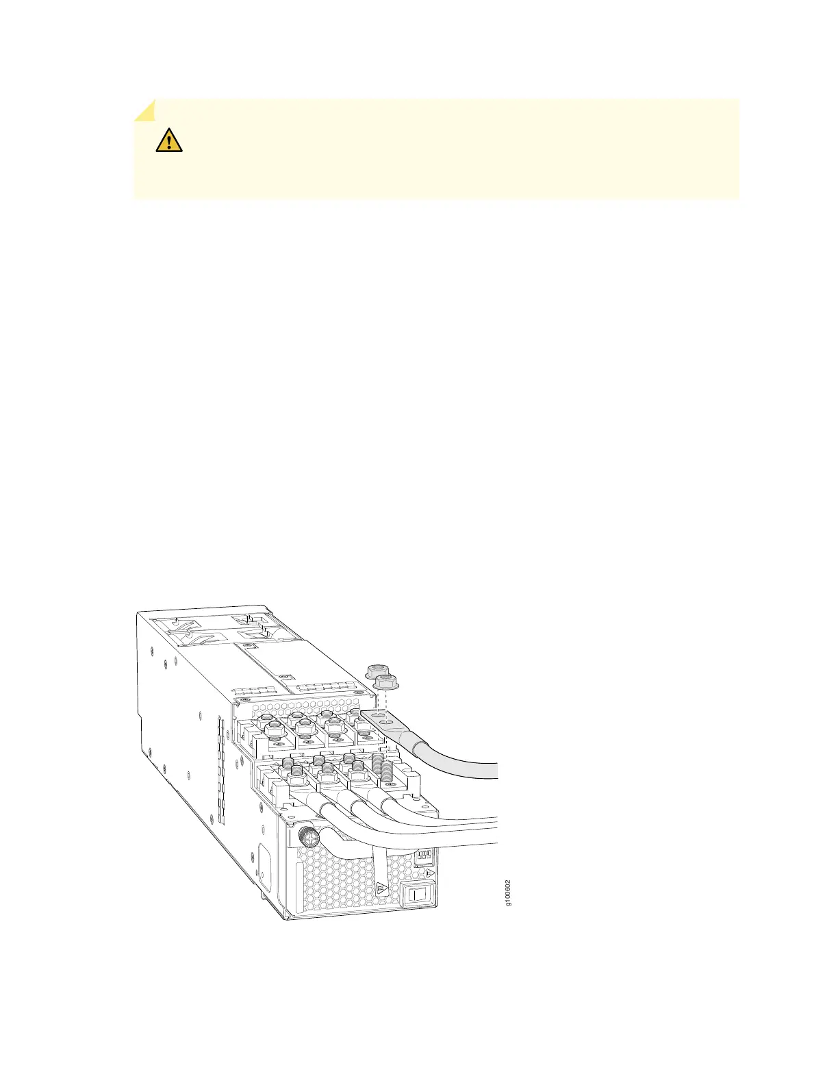
9. Install each power cable lug on the DC power input terminal, securing it with the nut (see
Figure 134 on page 238). Apply between 24 in.-lb (2.7 N-m) and 25 in.-lb (2.8 N-m) of torque to each
nut. (Use the 13/32 in. [10 mm] nut driver or socket wrench.)
a. Secure each positive (+) DC source power cable lug to the RTN (return) DC power input terminal.
b. Secure each negative (–) DC source power cable lug to the –48V (input) DC power input terminal.
Each power supply has two independent sets of DC power input terminals (INPUT 1: RTN –48V/–60V:
and INPUT 2: : RTN –48V/–60V). For feed redundancy, each power supply must be powered by
dedicated power feeds derived from feed INPUT 1 and feed INPUT 2. This configuration provides the
commonly deployed INPUT 1 / INPUT 2 feed redundancy for the router. There is basic insulation
between the inputs and the chassis ground. Also, there is basic insulation between RTN input feeds.
Figure 134: Connecting the DC Power Supply Cables to a JNP10K-PWR-DC2
238