3. Ensure that all grounding surfaces are clean and brought to a bright nish before grounding
connecons are made.
4. Connect the grounding cable to a proper earth ground.
5. Detach the ESD grounding strap from the site ESD grounding point.
6. Connect the grounding strap to one of the ESD points on the chassis. No Link Title shows the ESD
point on the router.
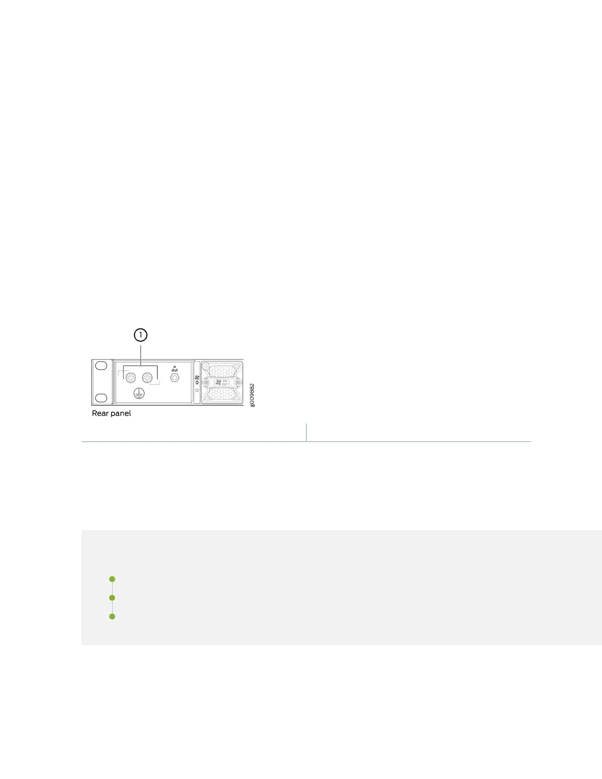
7. Place the grounding cable lug over the grounding point on the side of the chassis (see Figure 12 on
page 12).
8. Secure the grounding cable lug with the screws. The holes are sized to accommodate M5 Pan Head
screws.
9. Dress the grounding cable and verify that it does not touch or block access to router components,
and that it does not drape where people could trip on it.
Figure 12: Grounding Point on the MX204 Router
1—
Grounding point
Step 4: Connect External Devices and Cables
IN THIS SECTION
Connect the Router to a Network for Out-of-Band Management | 13
Connect the Router to a Console Device | 14
Connect the Router to External Clocking and Timing Devices | 16
Figure 13 on page 13 shows the front panel of the MX204 router. All the connecons to the router are
made through the front panel.
12