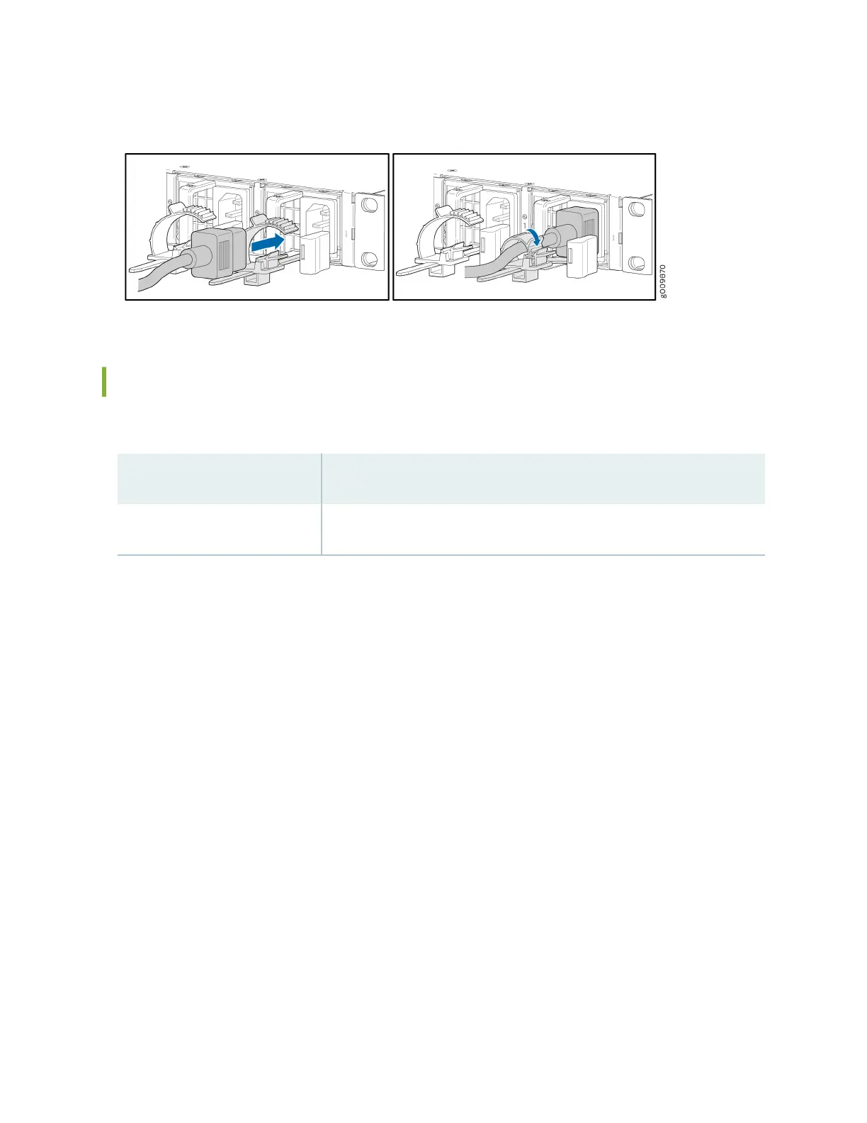
Figure 18: Connecng an AC Power Cord to an MX204 AC Power Supply
Connect Power to a DC Router
Table 8: MX204 DC Power System Input Voltage
Item Specicaon
DC input voltage Operang range: –44 through –72 VDC
1. Switch o the dedicated customer-site circuit breakers. Ensure that the voltage across the DC
power source cable leads is 0 V and that there is no chance that the cable leads might become
acve during installaon.
2. Remove the clear plasc cover protecng the terminal on the faceplate.
3. Verify that the DC power cables are correctly labeled before making connecons to the power
supply. In a typical power distribuon scheme where the return is connected to chassis ground at
the baery plant, you can use a mulmeter to verify the resistance of the –48V and RTN DC cables
to chassis ground:
• The cable with very large resistance (indicang an open circuit) to chassis ground is –48V.
• The cable with very low resistance (indicang a closed circuit) to chassis ground is RTN.
4. Remove the screws from the terminals.
5. Secure each power cable lug to the terminal with the screw (see Figure 19 on page 22). Apply
between 5 lb-in. (0.6 Nm) and 6 lb-in. (0.7 Nm) of torque to the screw. Do not overghten the nut.
(Use a number Phillips 2 screwdriver.)
a. Secure the posive (+) DC source power cable lug to the RTN (return) terminal.
b. Secure the negave (–) DC source power cable lug to the –48V (input) terminal.
20